When it comes to amateur radio, one size definitely does not fit all. That’s especially true with antennas, which need to be just the right size for the band you’re working, lest Very Bad Things happen to your expensive radio. That presents a problem for the ham who wants the option to work whichever band is active, and doubly so if portable operation is desired.
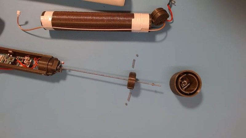
Of course, there are commercial solutions to this problem, but they tend to be expensive. Luckily [Øystein (LB8IJ)] seems to have found a way around that with this low-cost homebrew motorized antenna coil, which is compatible with the Yaesu Automatic Tuning Antenna System. ATAS is supported by several Yaesu transceivers, including the FT-891 which [Øystein] favors for field operations. ATAS sends signals up the feedline to a compatible antenna, which then moves a wiper along a coil to change the electrical length of the antenna, allowing it to resonate on the radio’s current frequency.
The video below details [Øystein]’s implementation of an ATAS-compatible tuning coil, mainly focusing on the mechanical and electrical aspects of the coil itself, which takes up most of the room inside a 50-mm diameter PVC tube. The bore of the air-core coil has a channel that guides a wiper, which moves along the length of the coil thanks to a motor-driven lead screw. [Øystein] put a lot of work into the wiper, to make it both mechanically and electrically robust. He also provides limit switches to make sure the mechanism isn’t over-driven.
There’s not much detail yet on how the control signals are detected, but a future video on that subject is promised. We’re looking forward to that, but in the meantime, the second video below shows [Øystein] using the tuner in the field, with great results.
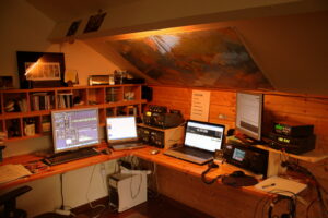
Full disclosure: ham radio isn’t for everyone, and there are many different facets to it. What appeals to one person might bore another to death. One area of ham radio that has changed a lot in the last few years is more or less local and typically mobile operation on VHF or UHF. Not long ago, hams used HTs (walky-talkies or handi-talkies) or mobile radios via repeaters to talk to each other and — the golden prize back then — make phone calls from their cars. Cell phones have made that much less interesting, but there is still an active community of operators talking on repeaters. However, the traffic has gone digital, the Internet is involved, and people with inexpensive, low-powered radios can talk to each other across the globe. This is nothing new, of course. However, having digital services means that operators with special interests can congregate in what amounts to radio chat rooms organized by region or topic.
There’s a long history of people listening to ham radio conversations with shortwave radios, SDRs, and scanners. But with so much activity now carried on the Internet, you can listen in using nothing more than your web browser or a phone app. I’ll show you how. If you get interested enough, it is easy enough to get your license. You don’t need any Morse code anymore, and a simple Technician class license in the United States is all you need to get going.
A Quick DMR Primer
There are several digital ham networks around and like real networks, you can have different physical transport layers and then build on top of that. For the purposes of this post, I’m going to focus on DMR (digital mobile radio) on the Brandmeister network which is very large and popular ham network. You won’t need a license nor will you need to sign up for anything as long as you are content to just listen.
Here’s how it works: Brandmeister operates a large number of servers worldwide that communicate with each other and provide calling services, including group calls. So, if we set up a Hackaday talk group (fictitious, by the way) on group 1337, interested people could connect to that talk group and have a conversation.
Since we are just going to listen, I’m going to skip some of the details, but the trick is how people get to talk to these networks. In general, there are three ways. The classic way is to use a digital radio to talk to a repeater that is connected to the network. The repeater may have one or more talk groups on all the time, or you might request access to one.
However, another way to connect your radio to a “hotspot” connected to the Internet. That is, more or less, a special form of repeater that is very low power, and you have complete control over it compared to a repeater on some faraway hill. However, if you don’t mind operating using just a computer, you don’t need a radio at all. You simply talk directly to the nearest server, and you are on the network. Some of your audio will go to other computers, and it may go over the airwaves via someone else’s hotspot or repeater.
Talk Groups
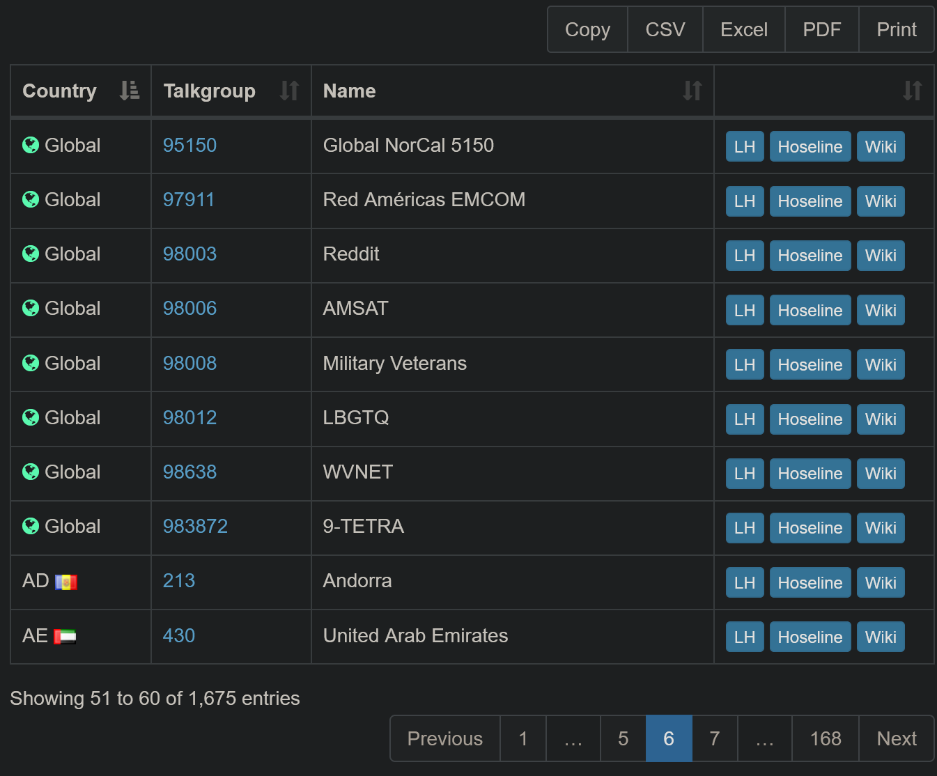
Just a few of the 1,600+ talkgroups available on the network
The Brandmeister website has a lot of info and you don’t need to be logged in to see it. Head over to their site and you’ll see a lot of info including a network map and statistics about repeaters and hotspots. You can get an idea of who has been talking lately by clicking Last Heard link. While this is interesting, it isn’t as interesting as you’d think, because you really want to focus on talk groups, not individual users.
To see a list of all the talk groups on the system, you can click Information and then Talkgroups. You can filter the list and you can also download the dataset in different formats if you want to browse it in a different format.
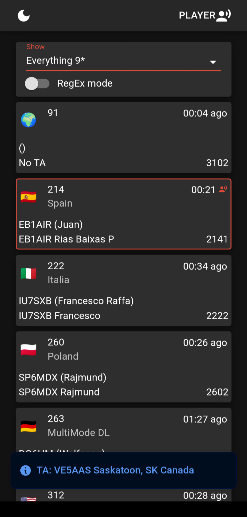
The hoseline shows you all the activity across the network and lets you listen in, too.
There are three buttons on each row of the database. The LH button shows you the last heard stations for that group. The Wiki button takes you to a Wiki page that, for some groups, has more information about it. But the really interesting button is the one marked Hoseline. You can also open the Hoseline directly which is what I usually do.
What’s the Hoseline? It shows activity across the network as a bunch of boxes indicating recently active talk groups. Boxes with red lines around them have people actively talking on them. The others have been recently active. It is visually interesting, yes, but that’s not the big selling point.
If you click on a box, you will hear the activity on that talk group. That’s all there is to it.
Overwhelming
There are a lot of talk groups. You can filter at the top left part of the page where it says “Everything.” You’ll have to drop the list down and unselect Everything. Then, you can select any countries or areas you want to follow. If you are brave, you can click RegEx mode and enter regular expressions to match talk group numbers (e.g. ^310.*).
The “Player” button at the top right gives you more control. You can add multiple groups from a list, see information about who is talking, and stop or start the audio.
The hose is available on Android, too.
If you prefer to do your listening mobile, you can also get the hoseline on your Android device. Just install the app, and you’ll find it works the same way.
Finding Something Interesting
Lord Nelson once said, “The greatest difficulty in war is not to win the battle, but to find the enemy.” That’s accurate here, too. Finding an interesting conversation out of all those talk groups is somewhat a needle in a haystack. A quick look around at the talk group lists might help.
The 91 and 93 groups stay busy but generally with short exchanges since they cover a wide area. The USA bridge at 3100 sometimes has traffic, too.
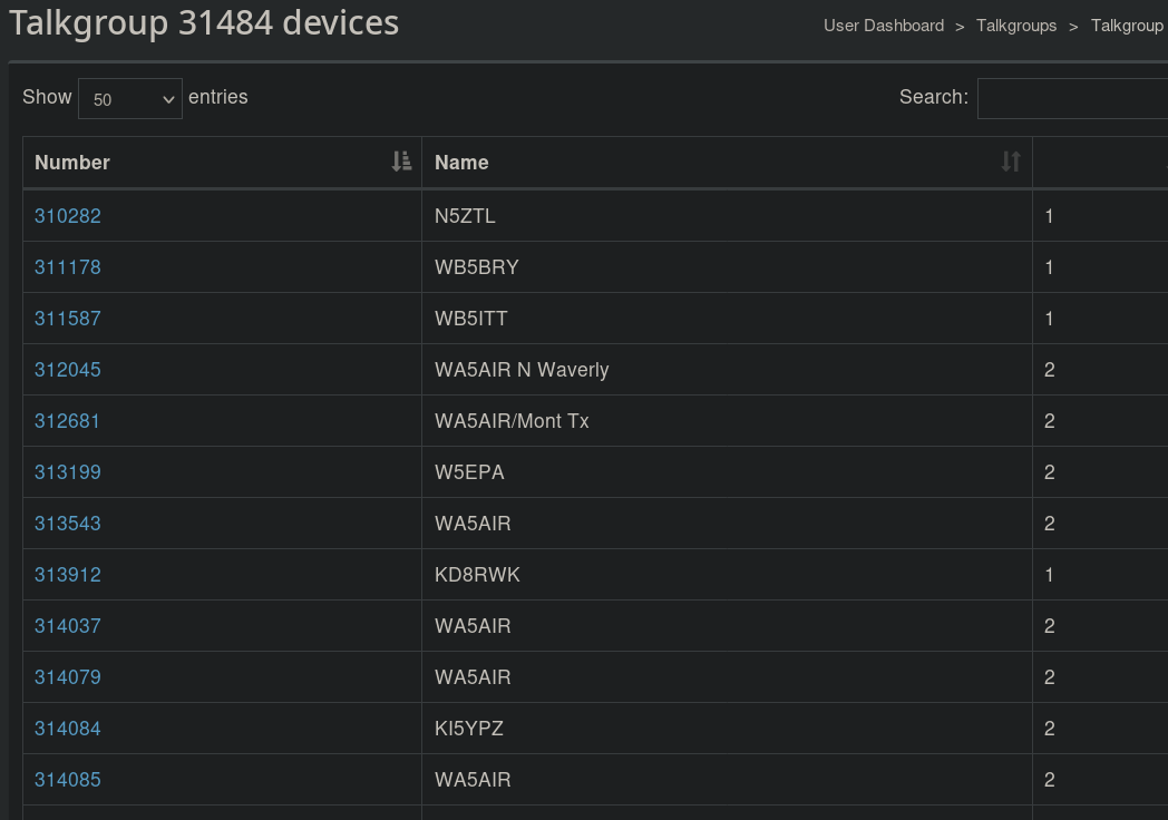
Talk group 31484 (SE Texas) has 66 devices attached, some of which you can see here.
If you look at the group’s listing on the Web, you can click the group number and see what stations are connected to it. Keep in mind, some of these may be repeaters or gateways that could have no one on the other side, or could have dozens of people on the other side. But it can give you an idea if the talkgroup has any users at all.
You can also search the Internet for DMR nets and repeaters. Sometimes, it is interesting to listen to local repeaters. Sometimes, it is fun to listen to repeaters in other places. Want to find out what’s going on at your next vacation spot? Practice your French?
There are many other similar networks, but they may not have a way to listen that doesn’t require some software, registration, or licenses. There’s plenty on Brandmeister to keep you busy. If you worry about people listening in, that’s no different than regular radio has been since the beginning.
You can always get your ham license and join in. Even without a radio, there are ways to talk on the network. [Dan Maloney] has advice for getting your “ticket.” It is easier than you think, and you can do a lot more with a license, including talking through satellites, sending TV signals over the air, and bouncing signals of meteors or the moon. If you want to listen to more traditional ham radio in your browser, try a Web-based SDR.
These days, anything with copper in it is expensive. If you doubt that, a walk into any Home Depot electrical department, where the wire is locked up tighter than Fort Knox, will prove otherwise. Coaxial cable is a particularly expensive species, which is a pity for hams and other radio enthusiasts since it’s the only thing we can use for antenna feedlines.
Or is it? [Steve (VE6WZ)] has found a way to use ordinary Cat 6 Ethernet cable for antenna feed lines that seems pretty clever. As he points out, Ethernet cables are designed to handle frequencies that coincide nicely with most of the interesting amateur radio bands, and their insertion losses are acceptably low, especially for Cat 6 cable. The twisted pairs are also a balanced system that’s good at rejecting common mode noise. Cat 6 cable also has four pairs of conductors, allowing you to feed multiple antennas with one cable, or to distribute power to amplifiers and switches along with antenna feeds.
The downside? Cat6 conductor pairs have a characteristic impedance of around 100 ohms, which isn’t a match for the 50-ohm feedline impedance universally expected by ham radios. Also, the relatively small wires probably aren’t up to the job of carrying much current, limiting their use to feedlines for receive-only antennas. That works for [Steve] since he uses Cat 6 to support his massive Beverage antenna farm (Beverage antennas are non-resonant horizontal antennas that live close to the ground and point in the direction of the signal, rather than broadside to the signal as with a resonant antenna like a dipole.) Each antenna in his farm has a transimpedance amplifier that needs to be powered, plus switching relays so he can turn the correct antennas on for the signals he wants to receive. He describes the amps in detail in the video below, along with the custom impedance-matching transformers he uses and the combining gear.
Coax will probably still be the cable of choice for most feedline applications, but it’s nice to know there are alternatives. And who knows—if you stick to QRP work, maybe Cat 6 could even be used for transmitting.
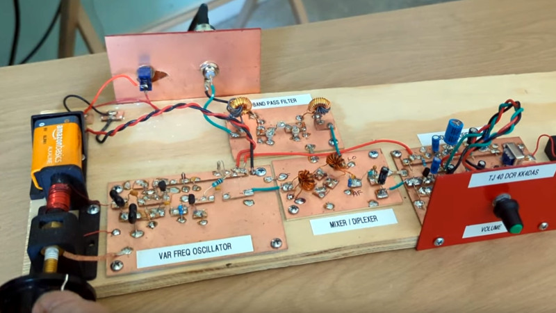
A couple of years ago one of the Hackaday Prize finalists was a project to take highschoolers through building a direct conversion radio receiver for the 40 metre amateur band. It was originated by the SolderSmoke podcast, and we’re pleased to see that they’ve recently put up an overview video taking the viewer through the whole project in detail.
It’s a modular design, with all the constituent building blocks broken out into separate boards on which the circuitry is built Manhattan style. Direct conversion receivers are pretty simple, so that leaves us with only four modules for oscillator, bandpass filter, mixer, and audio amplifier. We particularly like that it’s permeability tuned using a brass screw and an inductor, to make up for the once-ubiquitous variable capacitors now being largely a thing of the past.
A point that resonated was that most radio amateurs never make something like this. Arguments can be made about off-the-shelf rigs and chequebook amateurs, but we’d like to suggest that everyone can benefit from a feel for analogue circuitry even if they rarely have a need for a little receiver like this one. We like this radio, and we hope you will too after seeing the video below the break.
How do you know that your patch cables are good? For simple jumper wires, a multimeter is about all you need to know for sure. But things can get weird in the RF world, in which case you might want to keep these coaxial patch cable testing tips in mind.
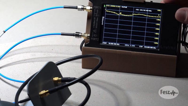
Of course, no matter how high the frequency, the basics still apply, and [FesZ] points out in the video below that you can still get a lot of mileage out of the Mark 1 eyeball and a simple DMM. Visual inspection of the cable and terminations can reveal a lot, as can continuity measurements on both the inner and outer conductors. Checking for shorts between conductors is important, too. But just because the cable reads good at DC doesn’t mean that problems aren’t still lurking. That’s when [FesZ] recommends breaking out a vector network analyzer like the NanoVNA. This tool will allow you to measure the cable’s attenuation and return loss parameters across the frequency range over which the cable will be used.
For stubborn problems, or just for funsies, there’s also time-domain reflectometry, which can be done with a pulse generator and an oscilloscope to characterize impedance discontinuities in the cable. We’ve covered simple TDR measurement techniques before, but [FesZ] showed a neat trick called time-domain transformation, which uses VNA data to visualize the impedance profile of the whole cable assembly, including its terminations.
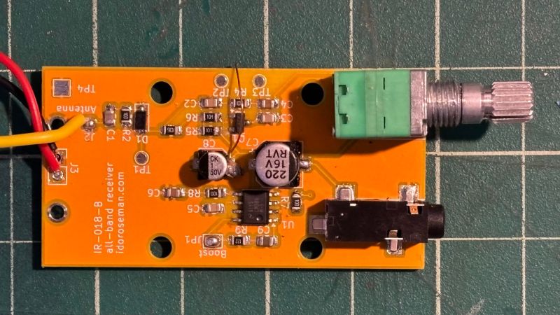
There are many ways to build a radio receiver, but most have a few things in common, such as oscillators, tuned circuits, detectors, mixers, and amplifiers. Put those together in the right order and you’ve got a receiver ready to tune in whatever you want to listen to. But if you don’t really care about tuning and want to hear everything all at once, that greatly simplifies the job and leaves you with something like this homebrew all-band receiver.
Granted, dispensing with everything but a detector and an audio amplifier will seriously limit any receiver’s capabilities. But that wasn’t really a design concern for [Ido Roseman], who was in search of a simple and unobtrusive way to monitor air traffic control conversations while flying. True, there are commercially available radios that tune the aviation bands, and there are plenty of software-defined radio (SDR) options, but air travel authorities and fellow travelers alike may take a dim view of an antenna sticking out of a pocket.
So [Ido] did a little digging and found a dead-simple circuit that can receive signals from the medium-wave bands up into the VHF range without regard for modulation. The basic circuit is a Schottky diode detector between an antenna and a high-gain audio amplifier driving high-impedance headphones; [Ido] built a variation that also has an LM386 amplifier stage to allow the use of regular earbuds, which along with a simple 3D-printed case aids in the receiver’s stealth.
With only a short piece of wire as an antenna, reception is limited to nearby powerful transmitters, but that makes it suitable for getting at least the pilot side of ATC conversations. It works surprisingly well — [Ido] included a few clips that are perfectly understandable, even if the receiver also captured things like cell phones chirping and what sounds like random sferics. It seems like a fun circuit to play with, although with our luck we’d probably not try to take it on a plane.
Een Duitse hacker heeft een satelliet tot leven weten te wekken die sinds 2013 niet meer werkte. Daarvoor hoefde PistonMiner niet naar de ruimte; de satelliet kon vanaf de grond weer worden gerepareerd door eerst de telemetrie te herstellen en daarna de originele code te hacken.
Hacker PistonMiner presenteerde de hack tijdens de CCC-hackersconferentie in Hamburg. Het gaat om de satelliet BeeSAT-1, wat staat voor de Berlin Experimental and Education Satellite. Dat is een kleine cubesat van 10x10x10cm die in 2009 door de Technische Universiteit van Berlijn werd gelanceerd. In 2011 begon de satelliet foutieve telemetrie terug te sturen naar de aarde. Nadat de beheerders de satelliet daarop overzetten naar de back-upcomputer, kreeg ook die in 2013 problemen. Sindsdien is de satelliet, die op een hoogte van 700 kilometer boven de aarde vliegt, niet meer bruikbaar. BeeSAT-1 stuurt namelijk alleen nog nullen door als telemetrie.
PistonMiner ontdekte al snel dat het niet mogelijk was om zomaar een firmware-update naar de satelliet te sturen. De functionaliteit daarvoor werd namelijk niet afgemaakt voor de lancering. Maar de hacker ontdekte ook dat de computer niet fysiek stuk was gegaan door bijvoorbeeld straling in de ruimte; in diens talk heeft PistonMiner het over softwareproblemen. De cubesat stuurt bijvoorbeeld data terug die corrupt lijkt te zijn. Dat kan in theorie gerepareerd worden in het flashgeheugen. PistonMiner ontdekte dat het probleem lag in de bootcounter van de computer aan boord. De hacker bouwde daarom een eigen BeeSAT hier op aarde om te simuleren of het probleem op afstand kon worden gerepareerd.
Daar kwam uit dat het mogelijk moest zijn om de vtables van de satellietsoftware, die in C++ werd geschreven, te onderscheppen. Zo kon PistonMiner commando’s uitvoeren op de satelliet zelf. In de talk vertelt de hacker ook hoe het mogelijk werd om de camera van de satelliet uiteindelijk te beheren. Die werkte aanvankelijk niet omdat er voorafgaand aan de lancering te weinig tijd was de firmware daarvoor te schrijven, maar PistonMiner kreeg het alsnog voor elkaar die bug te repareren en de camera werkend te krijgen.
PistonMiner vertelt in de talk verder ook hoe ingewikkeld het was om in de eerste plaats contact te leggen met de satelliet; die vliegt eens per anderhalf uur over Berlijn, waarin de hacker maximaal een kwartiertje de tijd had commando’s door te voeren naar de kleine cubesat. Uiteindelijk is dat wel gelukt. BeeSAT-1 is weer operationeel en kan worden gebruikt voor zijn originele doel om bijvoorbeeld signalen naar radioamateurs te sturen.
Update, 16.55uur – aangepast dat CCC in Hamburg plaatsvond en niet in Berlijn.
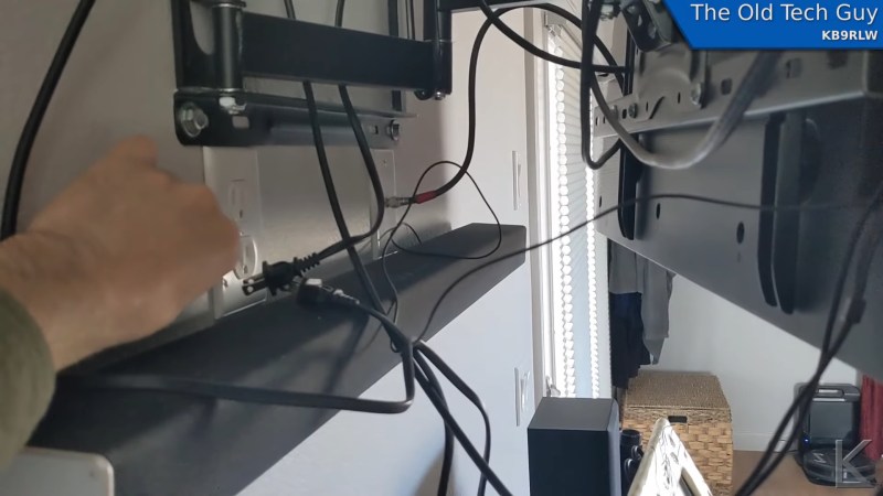
If there’s anything more annoying to an amateur radio operator than noise, we’re not sure what it could be. We’re talking about radio frequency noise, of course, the random broadband emissions that threaten to make it almost impossible to work the bands and pick out weak signals. This man-made interference is known as “QRM” in ham parlance, and it has become almost intolerable of late, as poorly engineered switch-mode power supplies have become more common.
But hams love a technical challenge, so when a nasty case of QRM raised its ugly head, [Kevin Loughlin (KB9RLW)] fought back. With an unacceptable noise floor of S8, he went on a search for the guilty party, and in the simplest way possible — he started flipping circuit breakers. Sure, he could have pulled out something fancier like a TinySA spectrum analyzer, but with his HF rig on and blasting white noise, it was far easier to just work through the circuits one by one to narrow the source down. His noise problem went away with the living room breaker, which led to pulling plugs one by one until he located the culprit: a Roomba vacuum’s charging station.
Yes, this is a simple trick, but one that’s worth remembering as at least a first pass when QRM problems creep up. It probably won’t help if the source is coming from a neighbor’s house, but it’s a least worth a shot before going to more involved steps. As for remediation, [Kevin] opts to just unplug the Roomba when he wants to work the bands, but if you find that something like an Ethernet cable is causing your QRM issue, you might have to try different measures.
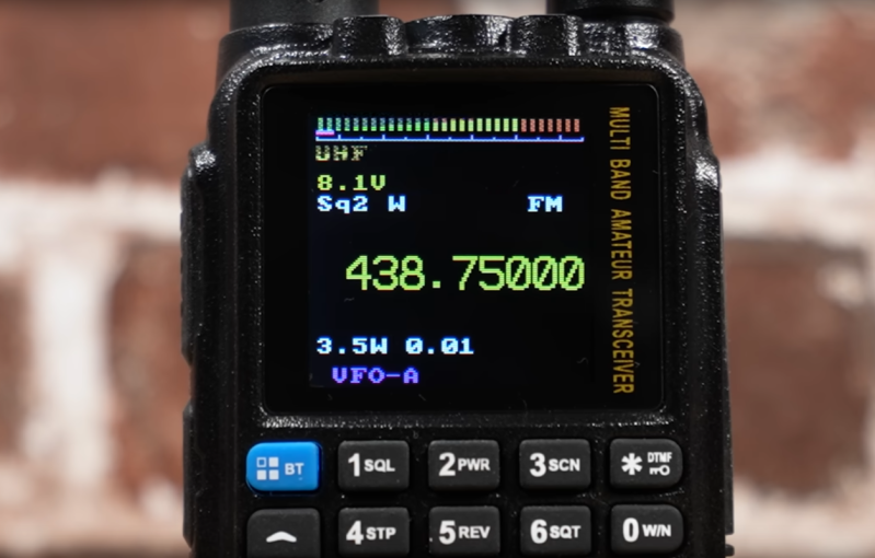
Although ham radio can be an engaging, rewarding hobby, it does have a certain reputation for being popular among those who would fit in well at gated Florida communities where the preferred mode of transportation is the golf cart. For radio manufacturers this can be a boon, as this group tends to have a lot of money and not demand many new features in their technology. But for those of us who skew a bit younger, there are a few radios with custom firmware available that can add a lot of extra capabilities.
The new firmware is developed by [NicSure] for the Tidradio TD-H3 and TD-H8 models and also includes a browser-based utility for flashing it to the radio without having to install any other utilities. Once installed, users of these handheld radios will get extras like an improved S-meter and detection and display of CTCSS tones for repeater usage. There’s also a programmer available that allows the radio’s memory channels to be programmed easily from a computer and a remote terminal of sorts that allows the radio to be operated from the computer.
One of the latest firmware upgrades also includes a feature called Ultra Graph which is a live display of the activity on a selected frequency viewable on a computer screen. With a radio like this and its upgraded firmware, a lot of the capabilities of radios that sell for hundreds of dollars more can be used on a much more inexpensive handheld. All of this is possible thanks to an on-board USB-C interface which is another feature surprisingly resisted by other manufacturers even just for charging the batteries.


 Een Duitse hacker heeft een satelliet tot leven weten te wekken die sinds 2013 niet meer werkte. Daarvoor hoefde PistonMiner niet naar de ruimte; de satelliet kon vanaf de grond weer worden gerepareerd door eerst de telemetrie te herstellen en daarna de originele code te hacken.
/i/2007162470.png?f=imagenormal)