The $50 Ham: Dummy Loads

This is an exciting day for me — we finally get to build some ham radio gear! To me, building gear is the big attraction of amateur radio as a hobby. Sure, it’s cool to buy a radio, even a cheap one, and be able to hit a repeater that you think is unreachable. Or on the other end of the money spectrum, using a Yaesu or Kenwood HF rig with a linear amp and big beam antenna to work someone in Antartica must be pretty cool, too. But neither of those feats require much in the way of electronics knowledge or skill, and at the end of the day, that’s why I got into amateur radio in the first place — to learn more about electronics.

To get my homebrewer’s feet wet, I chose perhaps the simplest of ham radio projects: dummy loads. Every ham eventually needs a dummy load, which is basically a circuit that looks like an antenna to a transmitter but dissipates the energy as heat instead of radiating it an appreciable distance. They allow operators to test gear and make adjustments while staying legal on emission. Al Williams covered the basics of dummy loads a few years back in case you need a little more background.

We’ll be building two dummy loads: a lower-power one specifically for my handy talkies (HTs) will be the subject of this article, while a bigger, oil-filled “cantenna” load for use with higher power transmitters will follow. Neither of my designs is original, of course; borrowing circuits from other hams is expected, after all. But I did put my own twist on each, and you should do the same thing. These builds are covered in depth on my Hackaday.io page, but join me below for the gist on a good one: the L’il Dummy.

L’il Dummy

As Al points out in the article linked above, a dummy load is just a resistive element that matches the characteristic impedance of the transmitter’s antenna connection. In almost every case, that’s going to be 50 ohms. The reason that the load needs to be as resistive as possible is that it needs to continue looking like a flat 50-ohm load no matter what frequency is applied to it. Any inductive or capacitive elements in the load will make it more reactive, changing the impedance as the input frequency changes. This could lead to RF power getting reflected back into the final amplifier transistors in the transmitter, possibly damaging them or destroying them altogether. Not what you’re looking for.

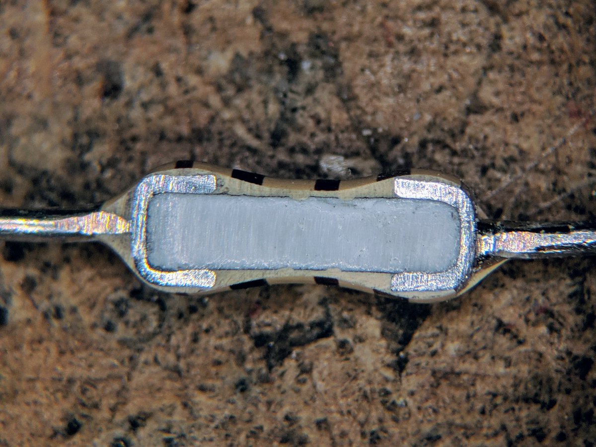
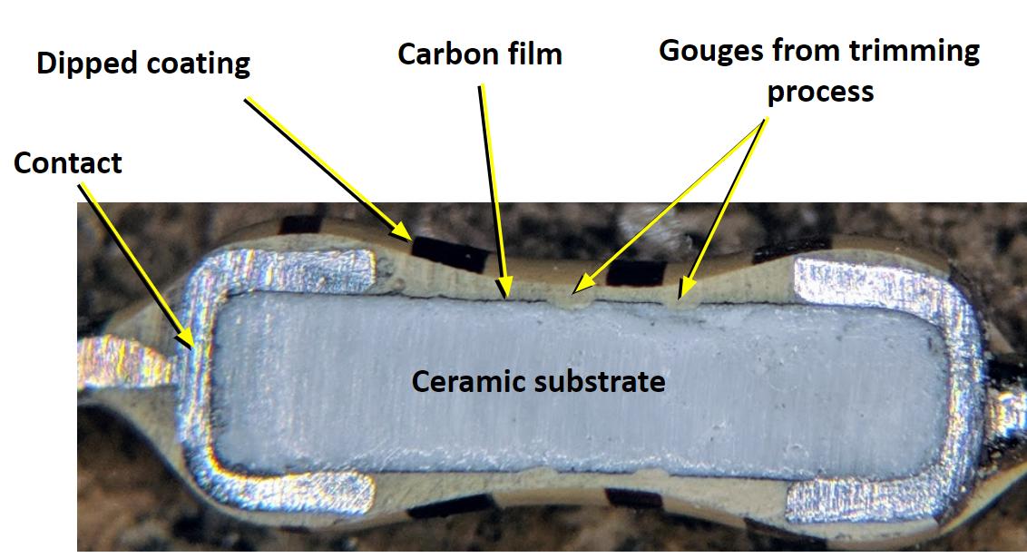
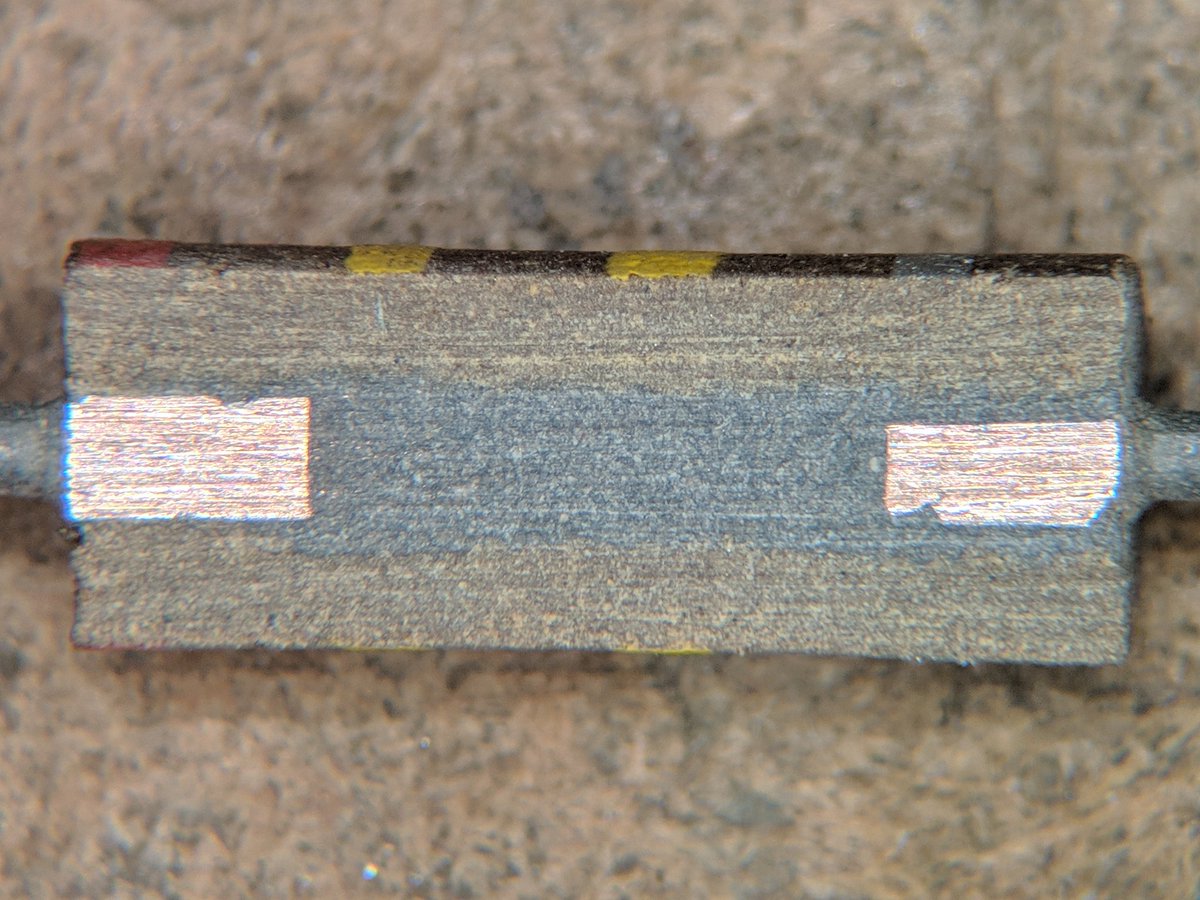
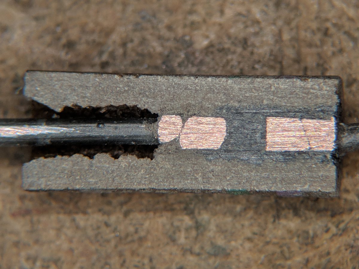
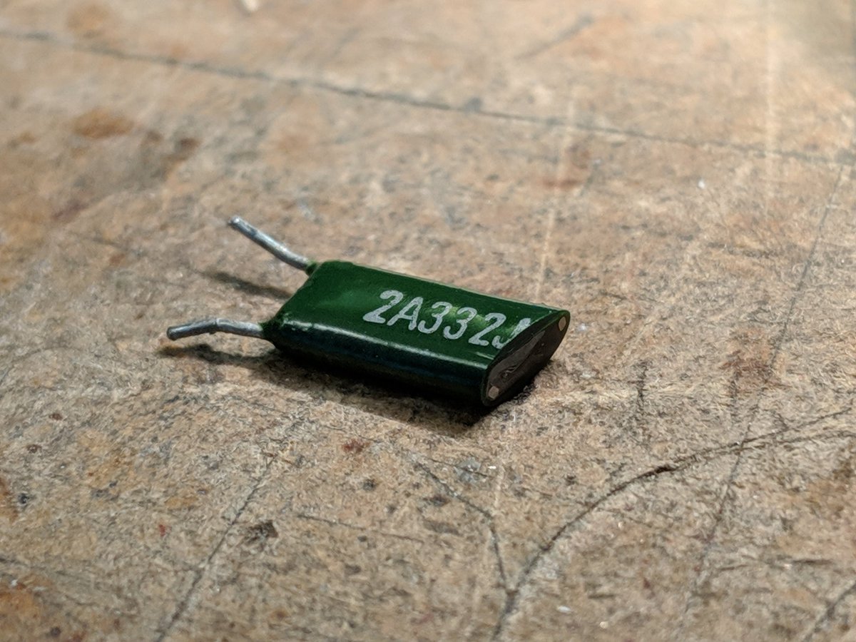
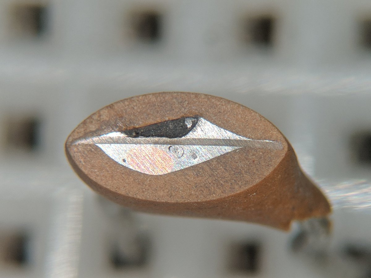
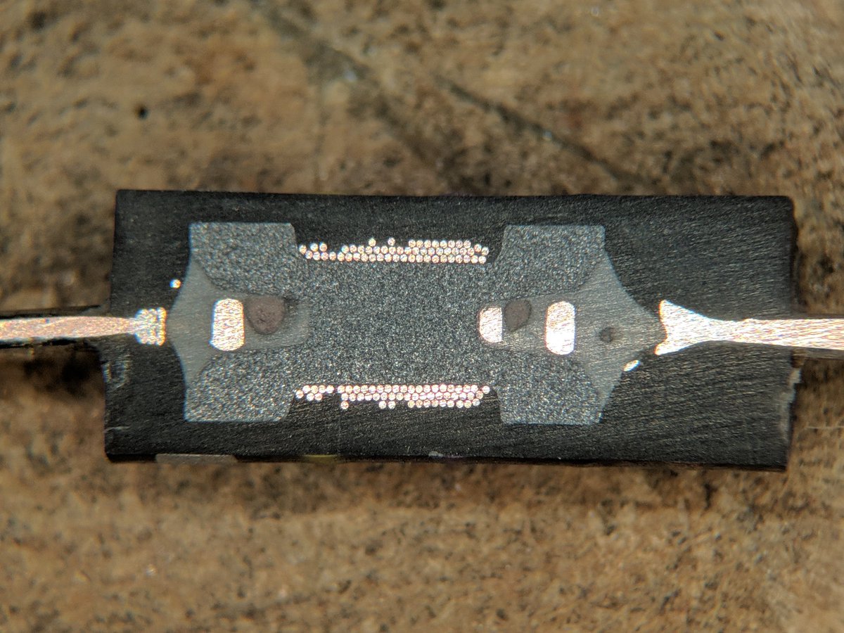
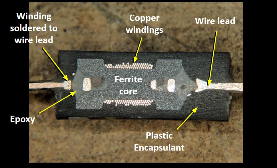
That means our resistive elements need to be as non-inductive as possible. But, they also need to be able to dissipate a lot of power. The HT dummy load, which I’ve dubbed L’il Dummy, needs to handle the 5 to perhaps 8 watts an HT can output. Trouble is, power resistors in that range are often wirewound, and a coil of wire will have too much inductance. We’ll need to be clever in sourcing components.

Looking down into L’il Dummy just before applying the torch. The RF Biscuit board is a handy little thing.

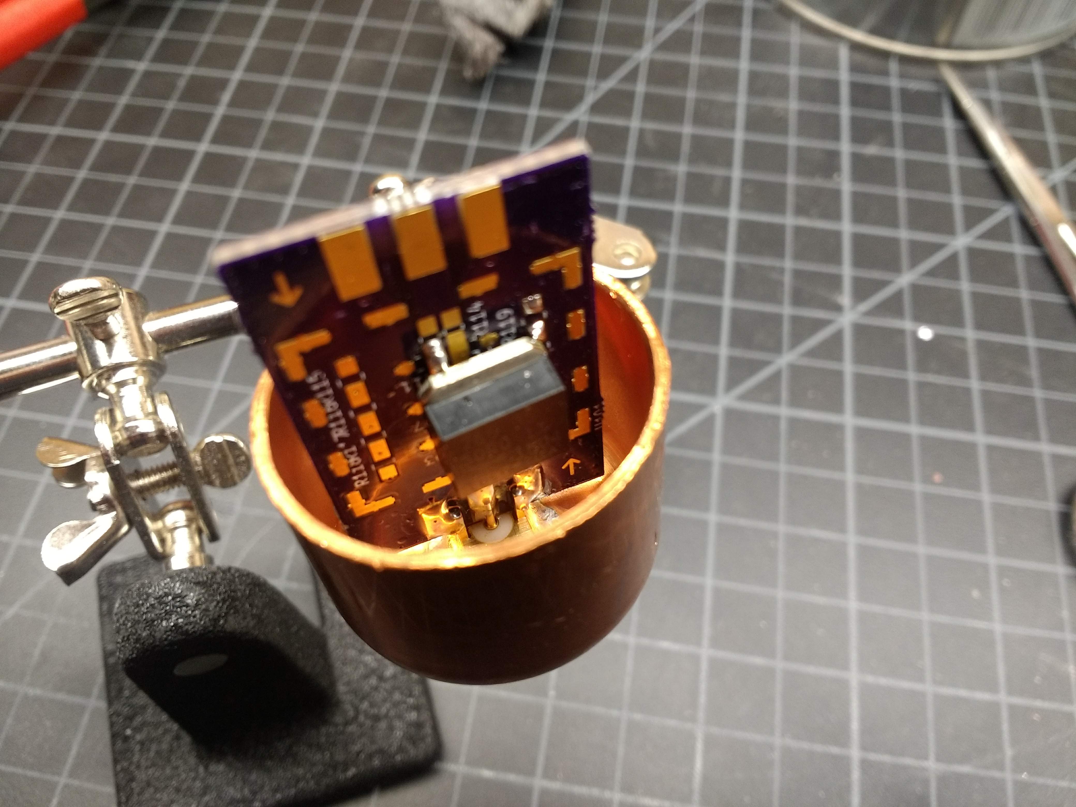
The circuit for L’il Dummy is hardly worth a schematic – it’s just an SMA jack with a 50-ohm resistor across the outer ground and the inner conductor. I chose to build the circuit on an RF Biscuit board. This is an open-source design that enables all kinds of handy little RF circuits — attenuators, filters, and as in this case, dummy loads. The resistive element I chose was a thick-film SMT device capable of dissipating 35 watts – way more than enough for this job. That and an edge-mount SMA jack should have been all I needed to make a working dummy load.

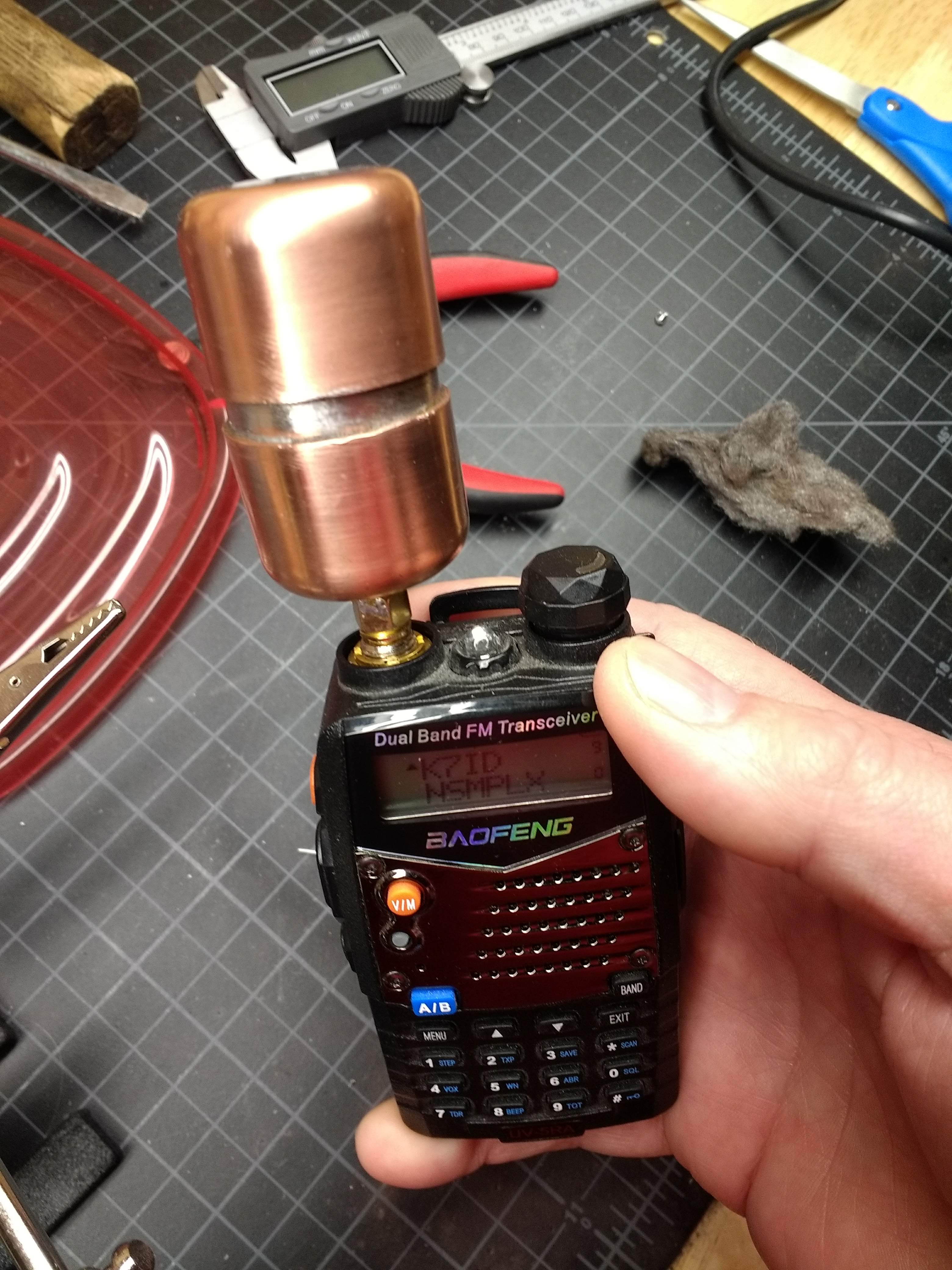
To my surprise, once I soldered the resistor to the RF Biscuit board, the dummy load was almost as good an antenna as the stock rubber ducky on my Baofeng HT. I was able to hit a local repeater through the dummy load without any issues. Clearly not a good design. To correct it, I put the whole thing into an enclosure made from 1″ copper pipe. Not cheap stuff, but not too bad, and I like the look of polished copper. Soldering the whole case together was a challenge that my big Weller soldering gun wasn’t up to, and trying to get everything heated up enough with a propane torch without overdoing the heat was a fun time.

Testing on a Budget

Now for the $50 question: does it work? I tested the resistance with a DMM and it comes out to just about 49 ohms, which is close enough in my book. But that’s DC resistance; what about impedance? I don’t have an antenna analyzer, so I trolled around and found a simple method for measuring impedance with only a function generator and an oscilloscope. My scope has a 20-MHz function generator built in, so I whipped up a quick test jig from a BNC jack and an SMA jack, connected in series through a leftover 1000-ohm resistor.

L’il Dummy test setup. Measure the p-p voltage on each side of the series resistance connecting the function generator to the dummy, and do a little math.

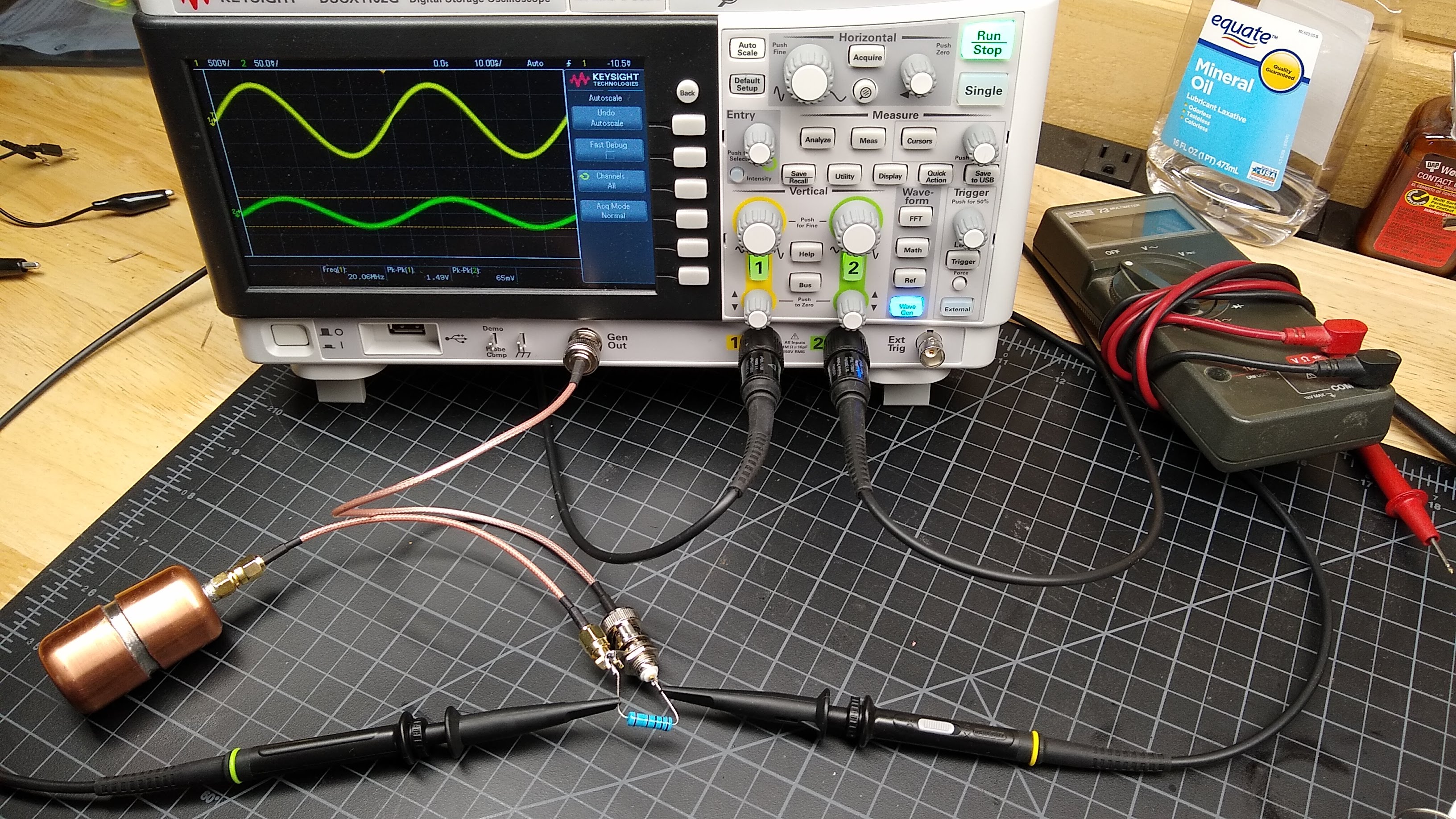
Applying a sine wave into the dummy load, measuring peak-to-peak voltages on each side of the resistance, and doing a little math is all that’s needed to characterize the impedance from 2.5 MHz to 20 MHz. The math is simple:

Z_x = \frac{V_2}{V_1 - V_2}R_{ref}

with V1 being the voltage across the input, V2 being the voltage across the output, and Rref being the actual value of the series resistance, which I measured at 998 Ohms.

And the results are pretty close to 50 Ohms, and flat across the tested band

f (MHz) V1 (V p-p) V2 (V p-p) Z (ohms)
20.0 1.49 0.062 43.3
15.0 1.89 0.082 45.3
10.0 2.57 0.113 45.9
5.0 3.90 0.173 46.3
2.5 4.70 0.217 48.3

I wish I could measure it at VHF and UHF frequencies, but that will have to wait until I get a function generator that goes up to 400 MHz or so. I doubt very much that a $50 budget would cover that, though.

Next Time

I had intended to cover both L’il Dummy and its bigger, somewhat smarter brother in one article, but I still have some testing to do on Big Dummy. I’ll cover that next time, and after that we’ll move onto measuring the output of a cheap Chinese HT and perhaps building a filter to clean it up.

BIJGEWERKT – Velddag Dairomont-Vielsalm v.a. 30 mei 2019

Na de succesvolle velddagen in Bellevaux is de VRZA Zuid-Limburg in 2018 verhuisd naar Dairomont, vlakbij Malmédy. Een uurtje rijden vanuit Maastricht ligt dit vakantiehuis bovenop een plateau met een prachtig uitzicht over de omgeving, zoals je op de foto kunt zien.

De velddag vindt in 2019 plaats vanaf donderdag 30 mei (Hemelvaartsdag) tot en met zondag 2 juni. Tijdens deze dagen zullen 8 leden van de VRZA hun kamp opslaan en met diverse antennes en transceivers proberen zoveel mogelijk verbindingen te maken en experimenten te doen.

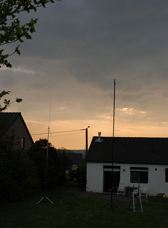
Net als vorig jaar zullen er een aantal antennes worden opgesteld voor de gebruikelijke HF banden en natuurlijk 2m en 70cm. Op die laatste band staat ON0TB altijd standby op 439.0125 MHz. De repeater PI3ZLB is vanuit Dairomont waarschijnlijk niet bereikbaar…

Zo laat in mei de velddag houden betekent een grotere kans op mooi en warm weer (check het weerbericht hier), een grotere kans op condities en daar zal gebruik van worden gemaakt! Diverse transceivers (én receivers) staan bijna volcontinue te snorren. Kortom: genoeg activiteit op de radio!

De velddag is natuurlijk ook door anderen te bezoeken. Hou er wel rekening mee dat er voor de maaltijden niet is gerekend op mee-eters dus zorg zelf voor eigen eten, indien nodig. Er zijn supermarkten genoeg in de buurt voor ad-hoc voedselvoorzieningen. Voor de consumpties wordt een bijdrage gevraagd. Wil je langs komen? Van harte welkom! Meld je even in via de repeater van Botrange: 439.0125 MHz (shift -7.6MHz), die staat continu aan tijdens de velddag. Nog beter: meld je vooraf aan tijdens een van de clubavonden en spreek af wanneer je komt zodat er rekening met je kan worden gehouden.
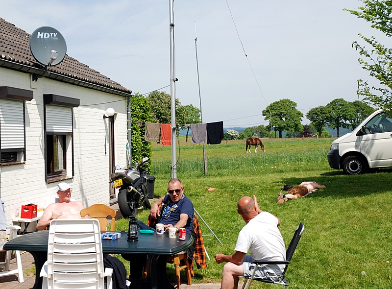
Parkeren in de buurt is geen probleem maar hou er rekening mee dat dit huisje in een gewoon dorp ligt dus hou rekening met omwonenden. De locatie is gewoon met de auto of motor te bereiken, je hoeft nu eens niet door het bos!

Klik even door naar de informatiepagina voor een complete routebeschrijving!

The $50 Ham: Checking Out the Local Repeater Scene

So far in this series, we’ve covered the absolute basics of getting on the air as a radio amateur – getting licensed, and getting a transceiver. Both have been very low-cost exercises, at least in terms of wallet impact. Passing the test is only a matter of spending the time to study and perhaps shelling out a nominal fee, and a handy-talkie transceiver for the 2-meter and 70-centimeter ham bands can be had for well under $50. If you’re playing along at home, you haven’t really invested much yet.

The total won’t go up much this week, if at all. This time we’re going to talk about what to actually do with your new privileges. The first step for most Technician-class amateur radio operators is checking out the local repeaters, most of which are set up exactly for the bands that Techs have access to. We’ll cover what exactly repeaters are, what they’re used for, and how to go about keying up for the first time to talk to your fellow hams.

Could You Repeat That?

Basic repeater schematic. Source: Ham Radio School

Time to face some cold, hard facts about amateur radio: that spiffy new Baofeng radio I recommended last time as a great starter radio is actually pretty lame. That fact has little to do with the mere $25 you spent on it, or $40 if you opted to upgrade the antenna. It’s a simple consequence of physics: a radio that transmits at 5 watts will only have so much range on the VHF band, and even less on UHF. Even if you buy a more powerful HT, or invest in a mobile or base-station rig running 50 or 100 watts, the plain fact is that direct radio-to-radio contacts on the same frequency, or simplex contacts, are difficult on VHF and UHF because those bands are really best for line of sight (LOS) use.

That’s not to say that hams don’t use their VHF and UHF rigs for simplex communications, of course. Many hams like to see just how far they can push their signals on these bands, building big Yagi antennas and finding mountain peaks to operate from. But for general use around town, most hams rely on repeaters to extend the area they can communicate over. Repeaters are simply transceivers set up to receive signals on one frequency and transmit them on another at the same time, with the help of a device called a duplexer. This simultaneous reception and transmission gives rise to the term duplex communications, the general term for operating on a repeater.

Repeater usually transmit at a much higher power than an HT or even a mobile rig can manage, and they usually have the advantage of being located on a mountaintop or some other elevated place to gain the furthest possible radio horizon as possible. This arrangement vastly increases the area that you can cover with your tiny HT. Depending on how the repeater is sited and what sort of antenna it has, you may be able to cover hundreds of square miles, as opposed to perhaps a few miles radius under ideal conditions, or a few blocks in the typical urban or suburban setting with lots of clutter from buildings and trees. What’s more, some repeaters are linked to other repeaters either through backhaul connections, often via the Internet but also sometimes through powerful LOS microwave links. In these systems it’s possible to use a puny HT to talk to another ham over hundreds or even thousands of miles. It’s actually pretty cool.

Welcome to the Machine

So where are these repeaters, and how do you start working them? The first question is easy to answer: they’re everywhere. Look at any tall building, mountaintop antenna farm, or municipal water tank, and chances are pretty good there’s a ham repeater there. But being able to work them means you need to know exactly where they are, to be sure you’re in range of the repeater, or “the machine” as hams often refer to it, as well as the frequencies it operates on.

Luckily, there are online guides to help with that chore. RepeaterBook.com is usually the first place hams go to find machines in the area. There you can search by state, county, or city, or even via a map, and find what repeaters are available. They’ve even got a handy road search, so you can get all the repeaters listed as within range of a particular highway; that’s really handy for road-trip planning. Here’s what comes up for VHF and UHF repeaters when I search within 25 miles of my location, or QTH:

The first thing you’ll notice is that several machines at different sites have the same callsign. For example, K7ID runs a UHF repeater on Canfield Mountain and a VHF machine on Mica Peak. Both are LOS to me, and I can easily hit them with an HT. The frequency listed in the first column is the transmit frequency of the repeater. Your HT will need to be set to this frequency to hear what’s being said. Your radio will also need to be programmed for the correct tone, listed in the third column. That tone is an audio frequency signal known by a number of different trade names, but generically as continuous tone-coded squelch system (CTCSS). Your radio is capable of adding this sub-audible tone to your transmission; the repeater will only “open up” to transmissions that are correctly coded. Some repeaters have no tone coding, others have different tones for receive and transmit. When doubt, try to find out who runs the machine – most, but not all, are run by a ham radio club – and see if you can look up instructions on the web.

The offset shown in the second column is perhaps the most important bit of information. Recall that repeaters transmit and receive on different frequencies, and that they’re listed by their transmit frequency. The offset tells you what the repeater’s input frequency is, which is the frequency your radio will need to be set to transmit on. For example, the machine I most often used is the K7ID machine on Mica Peak. It’s at 146.980 and shows an offset of -0.6 MHz. That means that my radio has to be set to 146.380 MHz transmission frequency. VHF repeaters are usually 0.6 MHz, but could be plus or minus depending on which part of the VHF band they’re in. UHF repeaters usually have +5 MHz offsets.

Note: I’m not going to cover programming your radio, because there are plenty of guides online that do a better job than I can. DuckDuckGo is your friend.

Casting the Net

Once you’ve found your local repeaters and programmed your radio, it’s time to get on the air. My advice is to spend the first few days just listening to one or more repeaters. Activity levels vary – some machines are hopping all day, and some are barely used except during the typical commuting hours. When you hear a conversation, try to get a feeling for the culture of the repeater. Every group of hams has a culture, and as we discussed in the first installment of the series, it’s not always a healthy culture. My local repeater belongs to the Kootenai Amateur Radio Society, as friendly and as inviting a group of people as I’ve ever heard on the air. After listening to them chat for a few weeks, I was more than ready to reach out to them.

But first, a word about kerchunking. If you want to know if you’re in range of a repeater, you can test it out. Most repeaters have a “squelch tail” that keeps the repeater on the air for several seconds before going back to sleep, and this can be used to check if you’re in range. Some repeaters even identify themselves, either with a synthesized voice or Morse code when they “wake up”.  So you might want to ping the repeater.

Kerchunking, or transmitting into a repeater without identifying yourself, is one of those bad habits that everyone seems to have. But FCC part 97 rules, which cover the amateur radio service, require operators to transmit their call sign when they start a transmission. So don’t kerchunk; a simple identification like “This is KC1DJT testing and clear” will suffice. Nobody is likely to take that as an invitation to chat, but they might give you a reception report.

Once you’re feeling confident enough, try making a contact. I highly recommend checking out the local traffic networks. Hams pride themselves on having the skills and equipment to communicate in an emergency, but that means little without practice to keep everything sharp. Nets allow hams to practice message passing skills and to test their gear on a regular basis. My local group has a network check-in every night that follows a standard script and usually attracts about 30 check-ins. Here’s a sample from a recent check-in:

I’ve become a regular on this net and a few others, mainly because I want to practice, but also to get over my mic shyness. There’s another reason too – I want people to recognize my voice and callsign. If there ever is an emergency in my area, I feel like it’ll be easier to pitch in or to get help if I need it if people hear a familiar voice.

Next Time

Over the next few installments, we’re finally going to get to what I think ham radio is all about at its core: homebrewing. We’ll be building a few simple projects to make that cheap HT a little better, and also build a few tools to help run the shack a little more efficiently.

11 mei 2019: Molendag

Op 11 mei is het Nationale Molendag, een dag waarop je verschillende molens in Nederland kunt bezoeken en kunt zien hoe vroeger – en ook nu nog – molens werk verzetten.

De VRZA Zuid-Limburg is die dag aanwezig bij de Tienhovenmolen in Bemelen (klik voor details) om met het station PA6TIEN mee te doen aan Mills On The Air 2019. Daarbij zijn diverse stations in binnen- en buitenland actief op diverse banden om verbindingen te maken met elkaar en natuurlijk met radiozendamateurs over de hele wereld.

PA6TIEN zal actief zijn op 40m en 2m en natuurlijk ook op andere banden, afhankelijk van condities. Het station zal actief zijn tussen +/- 11:00 en 17:00 uur.

Tijdens het bezoek van de molen is er natuurlijk ook gelegenheid om te komen kijken bij het radiostation.

Oefening Landmacht, 6 mei 2019

Tijdens de gezamenlijke lezing in februari is aangekondigd dat er in de week van 6 mei een oefening wordt gehouden in Zuid Limburg. Als zendamateurs zijn we benaderd met de vraag om op onze banden wat activiteit te maken die kan worden verwerkt in de oefening. Inmiddels begint het programma wat meer vorm te krijgen. De belangrijkste punten voor ons zijn:

  • Tussen maandag 6 mei circa 15 uur en dinsdag middag ca 15 uur: afwisselend een aantal korte rondes en mini contest met verschillende digitale modes, en op rustiger momenten baken uitzendingen
  • woensdag 7 mei test met reflectie van zendsignalen tegen gebouwen

Wat heb je hiervoor nodig?

  • Een vaste, portable of mobiele locatie van waaruit je het gebied Maastricht – Margraten kan bereiken op VHF/UHF
  • Zendontvanger op 2m en/of 70 cm met bij voorkeur FM en SSB, plus interface voor digitale modes
  • PC met software voor digitale modes: FLdigi, WSJT-X (versie 2), MixW (versie 3).
  • packet, APRS

De opzet is zodanig dat je voor kortere of langere tijd kan deelnemen, aan een of meerdere onderdelen.

Een deel van de informatie zal ook op de website a22.veron.nl worden gepubliceerd. Een ander deel met de details van de oefening is alleen bedoeld voor de deelnemers.

Wil je en kan je voor een deel of het geheel deelnemen, meldt je dan aan bij Tom  PC5D@home.nl

PS voor de software zie website van nl9222.home.xs4all.nl/digisoft.htm

Electrical Component Cross Sections

Tube Time @TubeTimeUS March 31, 2019 Take a look at these fascinating and educational cross sections of an LED, resistor, diode, capacitor, and more. (The images in this Moment created by TubeTimeUS are licensed under CC BY-SA 4.0: https://creativecommons.org/licenses/by-sa/4.0/)

here’s a cross section of an LED! it still works too. 20 replies 330 retweets 1,317 likes

LED cross section — now with annotations!

here’s a cross section of a resistor!

and here it is with labels on the important bits. you can see part of the spiral gouge left by the trimming equipment. during manufacture, this machine removes carbon film, increasing the resistance until it hits the target value.

compare that with this old-school carbon composition resistor. it’s just carbon powder inside a phenolic tube.

this carbon composition resistor has a value of 7.5 ohms. doesn’t take much carbon to get that resistance!

here’s the cross section of a diode! it’s a 1N4007. you can see the piece of silicon in the middle. the lumps on the wires help hold them in the plastic case.

here’s a cross section of a surface mount ceramic chip capacitor.

here’s the annotated version. i’ve drawn in lines over 4 of the capacitor plates near the bottom to make them a bit more clear.

cross section of a film capacitor.

cross section of a ceramic disc capacitor. you can see the ceramic disc right across the center.

check out this cross section of an inductor!

annotated version of the inductor cross section.

annotated cross section of a film capacitor.

cross section of an electrolytic capacitor! i’ll annotate it shortly.

adjusted the annotations to correct a mistake. the paper in between the layers of foil is not actually the dielectric! when soaked in electrolyte, it serves as the cathode (‘-‘ terminal). the dielectric is an oxide layer grown on the anode (‘+’ terminal).

top view cross section of an electrolytic capacitor.

Here’s a version with each plate colored in to make it easier to trace how they’re wrapped around each other.

here’s the cross section of a dipped tantalum capacitor.

annotated cross section.

cross section of a 15-turn potentiometer

close-up of the slider. this part moves left and right as you turn the adjustment screws.

annotated version of the 15-turn trimmer potentiometer cross section.

have a look at this cross section of a tact switch!

annotated diagram of a tact switch cross section. in the photo, the button is pushed down and the dome is shorting the center contact to the outside contacts. when you let go, the metal dome snaps up, making a tiny click and breaking the circuit.

ok this is the cross section of a 2N3904 NPN transistor. what’s that tiny little speck?

it’s the transistor silicon die! the little gold dollop on top is the emitter bond wire! the big metal slug underneath is the collector terminal.

annotated version of 2N3904 NPN transistor cross section.

here’s a cutaway view of a classic 12AX7 vacuum tube triode. discriminating musicians use these tubes in their guitar amplifiers — you’ve definitely heard the sound before!

this is the annotated cutaway diagram of the 12AX7 vacuum tube.

in the middle of this photo, you can see the coated filament wires entering the hollow cathode. the filament heats up the cathode. this produces an aura of electrons called the “space charge” region.

how about a closeup of the grid wires and the cathode? the white powder is oxides of barium, strontium, and calcium, which improves electron emission. the control grid, if biased negative, repels the electrons, caging them up. otherwise they pass through the grid to the plate.

here’s a cross section of an Ethernet transformer. inside a network adapter, there is one of these in between the Ethernet PHY chip and the cable, providing isolation and safety.

here’s the side view cross section of an Ethernet transformer.

annotated version of the Ethernet transformer cross section.

ok don’t try this one at home: this is a cross section of an LR44 alkaline button cell!

annotated cross section of the LR44 alkaline button cell.

A New Digital Mode For Radio Amateurs

There used to be a time when amateur radio was a fairly static pursuit. There was a lot of fascination to be had with building radios, but what you did with them remained constant year on year. Morse code was sent by hand with a key, voice was on FM or SSB with a few old-timers using AM, and you’d hear the warbling tones of RTTY traffic generated by mechanical teletypes.

By contrast the radio amateur of today lives in a fast-paced world of ever-evolving digital modes, in which much of the excitement comes in pushing the boundaries of what is possible when a radio is connected to a computer. A new contender in one part of the hobby has come our way from [Guillaume, F4HDK], in the form of his NPR, or New Packet Radio mode.

NPR is intended to bring high bandwidth IP networking to radio amateurs in the 70 cm band, and it does this rather cleverly with a modem that contains a single-chip FSK transceiver intended for use in licence-free ISM band applications. There is an Ethernet module and an Mbed microcontroller board on a custom PCB, which when assembled produces a few hundred milliwatts of RF that can be fed to an off-the-shelf DMR power amplifier.

Each network is configured around a master node intended to use an omnidirectional antenna, to which individual nodes connect. Time-division multiplexing is enforced by the master so there should be no collisions, and this coupled with the relatively wide radio bandwidth of the ISM transceiver gives the system a high usable data bandwidth.

Whether or not the mode is taken up and becomes a success depends upon the will of individual radio amateurs. But it does hold the interesting feature of relying upon relatively inexpensive parts, so the barrier to entry is lower than it might be otherwise. If you are wondering where you might have seen [F4HDK] before, we’ve previously brought you his FPGA computer.

Bidirectional IP with New Packet Radio

There are a few options if you want to network computers on amateur radio. There are WiFi hacks of sort, and of course there’s always packet radio. New Packet Radio, a project from [f4hdk] that’s now on hackaday.io, is unlike anything we’ve seen before. It’s a modem that’s ready to go, uses standard 433 ISM band chips, should only cost $80 to build, and it supports bidirectional IP traffic.

The introductory documentation for this project (PDF) lays out the use case, protocol, and hardware for NPR. It’s based on chips designed for the 433MHz ISM band, specifically the SI4463 ISM band radio from Silicon Labs. Off the shelf amplifiers are used, and the rest of the modem consists of an Mbed Nucleo and a Wiznet W5500 Ethernet module. There is one single modem type for masters and clients. The network is designed so that a master serves as a bridge between Hamnet, a high-speed mesh network that can connect to the wider Internet. This master connects to up to seven clients simultaneously. Alternatively, there is a point-to-point configuration that allows two clients to connect to each other at about 200 kbps.

Being a 434 MHz device, this just isn’t going to fly in the US, but the relevant chip will work with the 915 MHz ISM band. This is a great solution to IP over radio, and like a number of popular amateur radio projects, it started with the hardware hackers first.