Velddag 2018: Dairomont (nabij Malmédy)

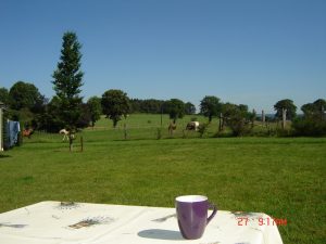
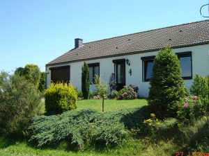
Na de succesvolle velddagen in Bellevaux is de VRZA Zuid-Limburg in 2018 verhuisd naar Dairomont, vlakbij Malmédy. Een uurtje rijden vanuit Maastricht ligt dit vakantiehuis bovenop een plateau met een prachtig uitzicht over de omgeving, zoals je op de foto kunt zien.

De velddag vindt plaats vanaf donderdag 10 mei (Hemelvaartsdag) tot en met zondag 13 mei. Tijdens deze dagen zullen 8 leden van de VRZA hun kamp opslaan en met diverse antennes en transceivers proberen zoveel mogelijk verbindingen te maken en experimenten te doen.


De velddag is natuurlijk ook te bezoeken. Hou er wel rekening mee dat er voor de maaltijden niet is gerekend op mee-eters dus zorg zelf voor eigen eten, indien nodig. Voor de consumpties wordt een bijdrage gevraagd. Wil je langs komen? Van harte welkom! Meld je even in via de repeater van Botrange: 439.0125 MHz (shift -7.6MHz, Tone – 131,8Hz), die staat continu aan tijdens de velddag.

Parkeren in de buurt zal geen probleem zijn maar hou er rekening mee dat dit huisje in een gewoon dorp ligt dus hou rekening met omwonenden. De locatie is gewoon met de auto of motor te bereiken, je hoeft nu eens niet door het bos!

Weersverwachting

Weersverwachting
Vielsalm

Weeronline.nl – Meer weer in Vielsalmweeronline.nl Altijd jouw weer


Het adres: Dairomont 27, 6698 Vielsalm, België: 

Route
U volgt de A2 richting Maastricht – Luik
Net voor Luik neemt u de autosnelweg
Antwerpen – Luik – Aaken
(hier opletten, kort na elkaar juiste afslag kiezen! (Aaken-Vervier)
Na ± 10 km volgt u de autosnelweg richting Verviers – Spa – St. Vith.
Bij afslag Malmedy gaat u rechts richting Stavelot en daarna Trois-Ponts
(na 2 tunnels linksaf, daarna weg volgen)
In Trois-Ponts volgt u richting Hamoir – Huy.
(Neem bij voorkeur deze route. Uw navigatiesysteem geeft mogelijk
de kortste route (langs de kerk) aan! Deze is echter alleen toegestaan
voor lokaal verkeer en erg steil en smal!)

Even buiten de bebouwde kom van Trois-Ponts gaat u de eerste weg links
(bord richting Fosse sur Salm).
U volgt deze weg via Mont de Fosse en Bergeval en u nadert dan Mont Saint Jacques.
Bij het eerste huis links van de weg ± 50m voor de kerk gaat u bij de kruising (richting Vielsalm) linksaf.
Het eerstvolgende huis links van de weg is uw vakantiebestemming!
(Nabij het kerkje van Mont Saint Jacques, dus wat afwijkend van punt A op het kaartje hierboven op deze pagina!)

Temperature Sensor and Simple Oscillator Make a Value-Added HF Beacon

Sometimes the best projects are the simple, quick hits. Easily designed, fast to build, and bonus points for working right the first time. Such projects very often lead to bigger and better things, which appears to be where this low-power temperature beacon is heading.

In the world of ham radio, beacon stations are transmitters that generally operate unattended from a known location, usually at limited power (QRP). Intended for use by other hams to determine propagation conditions, most beacons just transmit the operator’s call sign, sometimes at varying power levels. Any ham that can receive the signal will know there’s a propagation path between the beacon and the receiver, which helps in making contacts. The beacon that [Dave Richards (AA7EE)] built is not a ham beacon, at least not yet; operating at 13.56 MHz, it takes advantage of FCC Part 15 regulations regarding low-power transmissions rather than the Part 97 rules for amateur radio. The circuit is very simple — a one-transistor Colpitts oscillator with no power amplifier, and thus very limited range. But as an added twist, the oscillator is keyed by an ATtiny13 hooked to an LM335 temperature sensor, sending out the Celsius and Fahrenheit temperature in Morse every 30 seconds or so. The circuit is executed in Manhattan style, which looks great and leaves plenty of room for expansion. [Dave] mentions adding a power amp and a low-pass filter to get rid of harmonics and make it legal in the ham bands.

Beacons are just one of the ways for hams to get on the air without talking. Another fun way to analyze propagation is WSPR, which is little like an IoT beacon.


SDR IF Experiments

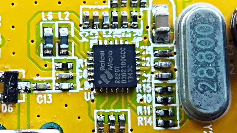
The R820T tuner IC is used in the popular Airspy software defined radio (SDR) as well as many of the inexpensive RTL SDR dongles. [TLeconte] did some experiments on intermediate frequency (IF) configuration of the chip, and you’ll find his results interesting.

Using 5 million samples per second and the device’s real mode, the tests look at a what comes out when the IC reads a noise source. There are two registers that set the IF parameters, but the tests show the effects these registers have in precise terms.

According to the post, there are three things you can set:

  • Coarse IF filter bandwidth : narrow/mid/large
  • Manual fine tuning IF filter bandwidth from 0 (large) to 15 (narrow)
  • High pass filter frequency from 0 (high) to 15 (low)

Some of the settings don’t make sense — at least at the 5 MHz sample rate — because of aliasing. However, it is instructive to see what each setting does. [TLeconte] uses Octave to visualize the data.

If you want to know more about SDR in general, we have something to get you started. If you want to do your own testing, consider using GNU Radio.

An SSB Transceiver Using Only One Device? Surely not!

There are a multiplicity of transmission modes both new and old at the disposal of a radio amateur, but the leader of the pack is still single-sideband or SSB. An SSB transmitter emits the barest minimum of RF spectrum required to reconstitute an audio signal, only half of the mixer product between the audio and the RF carrier, and with the carrier removed. This makes SSB the most efficient of the analog voice modes, but at the expense of a complex piece of circuitry to generate it by analog means. Nevertheless, radio amateurs have produced some elegant designs for SSB transmitters, and this one for the 80m band from [VK3AJG] is a rather nice example even if it isn’t up-to-the-minute. What makes it rather special is that it relies on only one type of device, every one of its transistors is a BC547.

In design terms, it follows the lead set by other simple amateur transmitters, in that it has a 6 MHz crystal filter with a mixer at either end of it that switch roles on transmit or receive. It doesn’t use the bidirectional amplifiers popularised by VU2ESE’s Bitx design, instead, it selects transmit or receive using a set of diode switches. The power amplifier stretches the single-device ethos to the limit, by having multiple BC547s in parallel to deliver about half a watt.

While this transmitter specifies BC547s, it’s fair to say that many other devices could be substituted for this rather aged one. Radio amateurs have a tendency to stick with what they know and cling to obsolete devices, but within the appropriate specs a given bipolar transistor is very similar to any other bipolar transistor. Whatever device you use though, this design is simple enough that you don’t need to be a genius to build one.

Via [G4USP]. Thanks [2ftg] for the tip.