With music consumption having long ago moved to a streaming model in many parts of the world, it sometimes feels as though, just like the rotary telephone dial, kids might not even know what a radio was, let alone own one. But there was a time when broadcasting pop music over the airwaves was a deeply subversive activity for Europeans at least, as the lumbering state monopoly broadcasters were challenged by illegal pirate stations carrying the cutting edge music they had failed to provide. [Ringway Manchester] has the story of one such pirate station which broadcast across the city for a few years in the 1970s, and it’s a fascinating tale indeed.
It takes the form of a series of six videos, the first of which we’ve embedded below the break. The next installment is placed as an embedded link at the end of each video, and it’s worth sitting down for the full set.
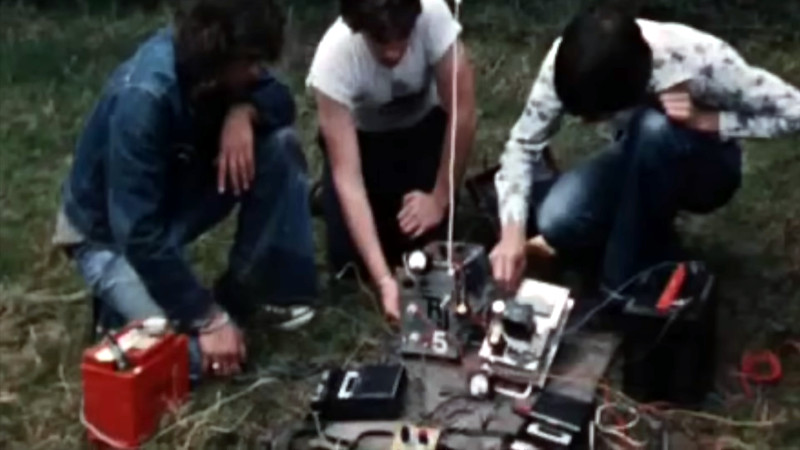
The action starts in early 1973 when a group of young radio enthusiast friends, left without access to a station of their taste by Government crackdowns on ship-based pirate stations, decided to try their hand with a land-based alternative. Called Radio Aquarius, it would broadcast on and off both the medium wave (or AM) and the FM broadcast bands over the next couple of years. Its story is one of improvised transmitters powered by car batteries broadcasting from hilltops, woodland, derelict houses, and even a Cold War nuclear bunker, and develops into a cat-and-mouse game between the youths and the local post office agency tasked with policing the spectrum. Finally having been caught once too many times, they disband Radio Aquarius and go on to careers in the radio business.
The tale has some tech, some social history, and plenty of excitement, but the surprise is in how innocent it all seems compared to the much more aggressively commercial pirate stations that would be a feature of later decades. We’d have listened, had we been there!
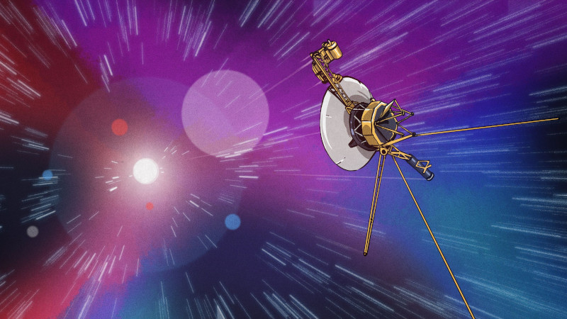
The tech news channels were recently abuzz with stories about strange signals coming back from Voyager 1. While the usual suspects jumped to the usual conclusions — aliens!! — in the absence of a firm explanation for the anomaly, some of us looked at this event as an opportunity to marvel at the fact that the two Voyager spacecraft, now in excess of 40 years old, are still in constant contact with those of us back on Earth, and this despite having covered around 20 billion kilometers in one of the most hostile environments imaginable.
Like many NASA programs, Voyager has far exceeded its original design goals, and is still reporting back useful science data to this day. But how is that even possible? What 1970s-era radio technology made it onto the twin space probes that allowed it to not only fulfill their primary mission of exploring the outer planets, but also let them go into an extended mission to interstellar space, and still remain in two-way contact? As it turns out, there’s nothing magical about Voyager’s radio — just solid engineering seasoned with a healthy dash of redundancy, and a fair bit of good luck over the years.
The Big Dish
For a program that in many ways defined the post-Apollo age of planetary exploration, Voyager was conceived surprisingly early. The complex mission profile had its origins in the “Planetary Grand Tour” concept of the mid-1960s, which was planned to take advantage of an alignment of the outer planets that would occur in the late 1970s. If launched at just the right time, a probe would be able to reach Jupiter, Saturn, Uranus, and Neptune using only gravitational assists after its initial powered boost, before being flung out on a course that would eventually take it out into interstellar space.
The idea of visiting all the outer planets was too enticing to pass up, and with the success of the Pioneer missions to Jupiter serving as dress rehearsals, the Voyager program was designed. Like all NASA programs, Voyager had certain primary mission goals, a minimum set of planetary science experiments that project managers were reasonably sure they could accomplish. The Voyager spacecraft were designed to meet these core mission goals, but planners also hoped that the vehicles would survive past their final planetary encounters and provide valuable data as they crossed the void. And so the hardware, both in the spacecraft and on the ground, reflects that hope.
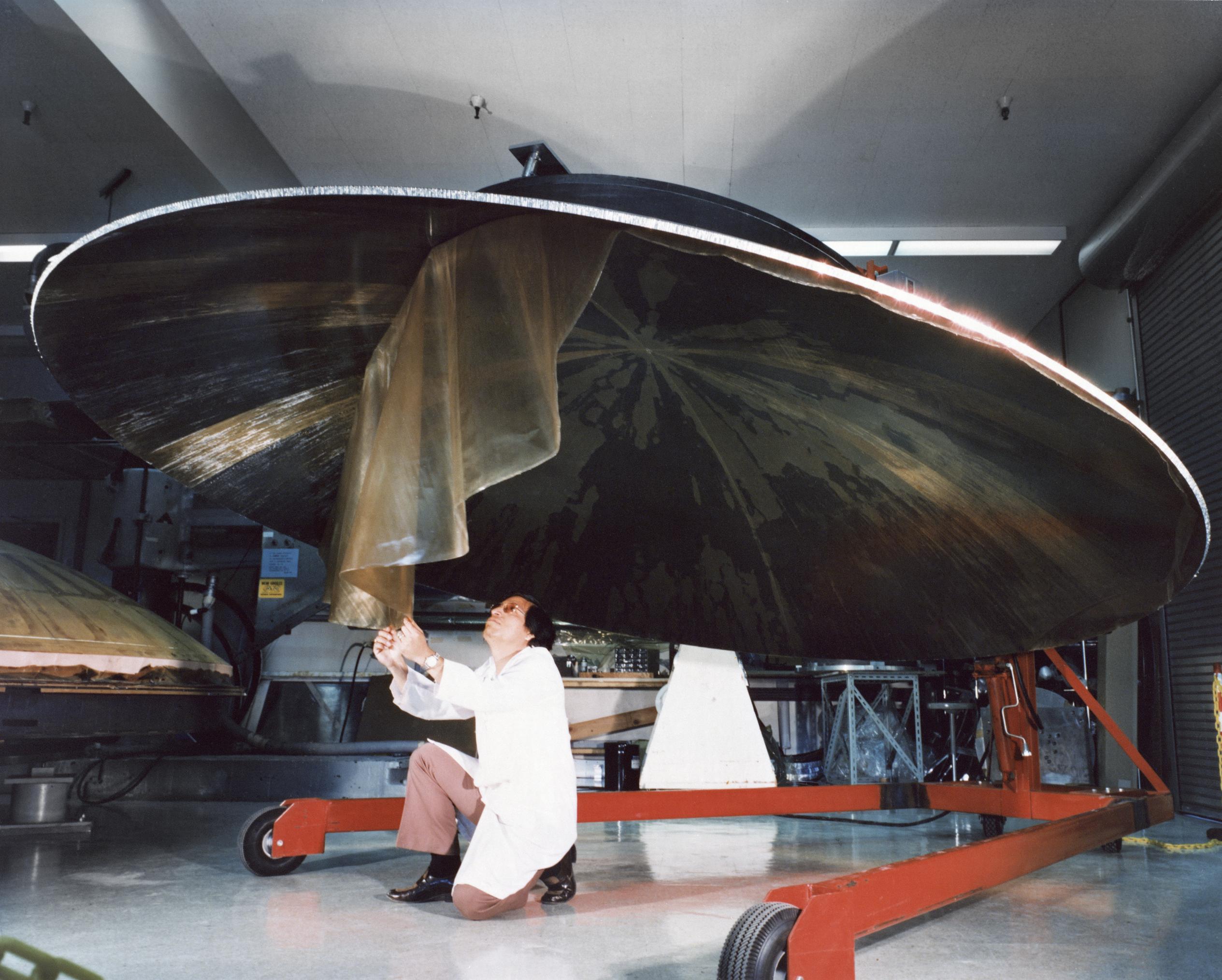
Voyager primary reflector being manufactured, circa 1975. The body of the dish is made from honeycomb aluminum and is covered with graphite-impregnated epoxy laminate skins. The surface precision of the finished dish is 250 μm. Source: NASA/JPL
The most prominent physical feature of both the ground stations of the Deep Space Network (DSN), which we’ve covered in-depth already, and the Voyager spacecraft themselves are their parabolic dish antennas. While the scale may differ — the DSN sports telescopes up to 70 meters across — the Voyager twins were each launched with the largest dish that could fit into the fairing of the Titan IIIE launch vehicle.
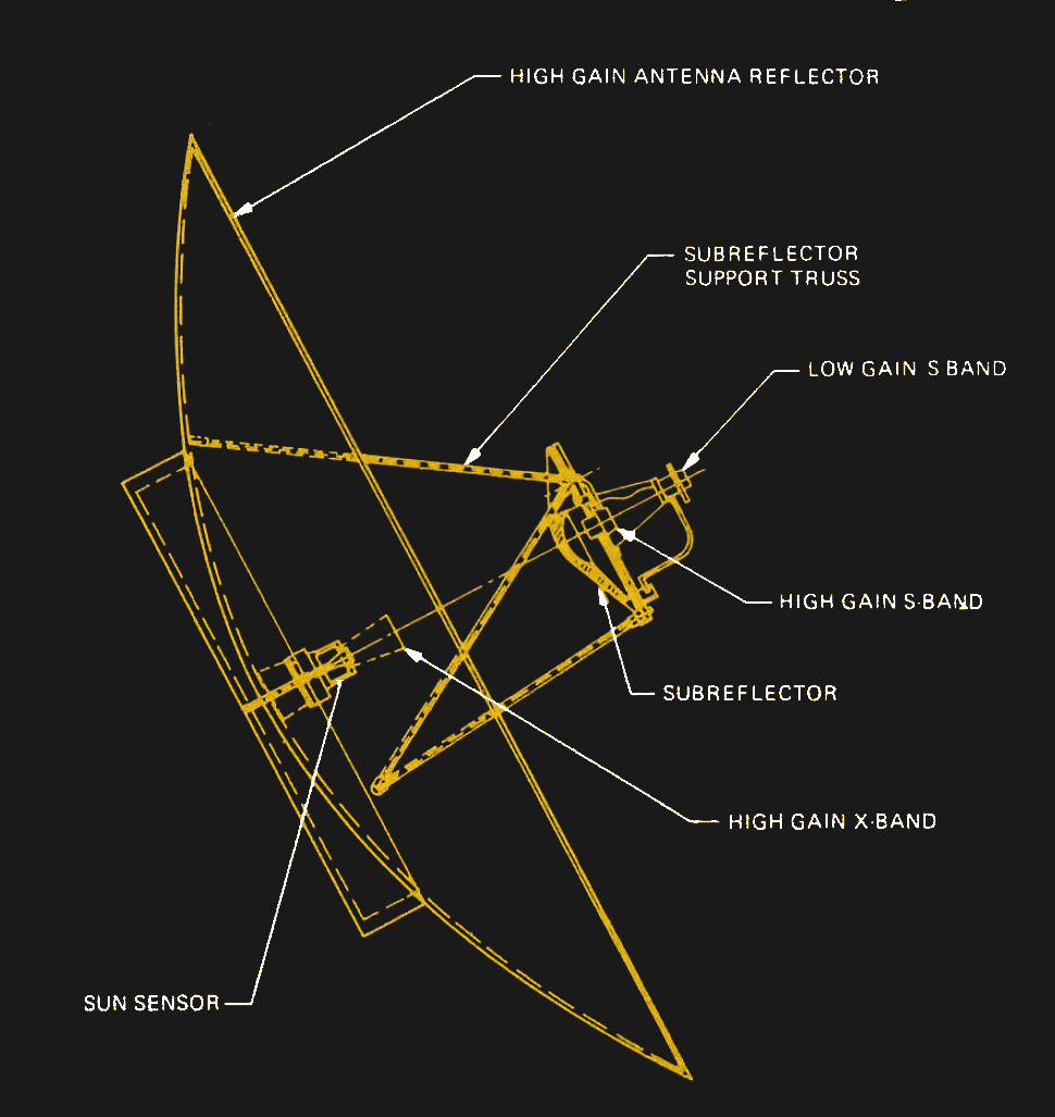
Voyager High-Gain Antenna (HGA) schematic. Note the Cassegrain optics, as well as the frequency-selective subreflector that’s transparent to S-band (2.3-GHz) but reflects X-band (8.4-GHz). Click to enlarge. Source: NASA/JPL
The primary reflector of the High Gain Antenna (HGA) on each Voyager spacecraft is a parabolic dish 3.7 meters in diameter. The dish is made from honeycomb aluminum that’s covered with a graphite-impregnated epoxy laminate skin. The surface of the reflector is finished to a high degree of smoothness, with a surface precision of 250 μm, which is needed for use in both the S-band (2.3 GHz), used for uplink and downlink, and X-band (8.4 GHz), which is downlink only.
Like their Earth-bound counterparts in the DSN, the Voyager antennas are a Cassegrain reflector design, which uses a Frequency Selective Subreflector (FSS) at the focus of the primary reflector. The subreflector focuses and corrects incoming X-band waves back down toward the center of the primary dish, where the X-band feed horn is located. This arrangement provides about 48 dBi of gain and a beamwidth of 0.5° on the X-band. The S-band arrangement is a little different, with the feed horn located inside the subreflector. The frequency-selective nature of the subreflector material allows S-band signals to pass right through it and illuminate the primary reflector directly. This gives about 36 dBi of gain in the S-band, with a beamwidth of 2.3°. There’s also a low-gain S-band antenna with a more-or-less cardioid radiation pattern located on the Earth-facing side of the subreflector assembly, but that was only used for the first 80 days of the mission.
Two Is One
Three of the ten bays on each Voyager’s bus are dedicated to the transmitters, receivers, amplifiers, and modulators of the Radio Frequency Subsystem, or RFS. As with all high-risk space missions, redundancy is the name of the game — almost every potential single point of failure in the RFS has some sort of backup, an engineering design decision that has proven mission-saving in more than one instance on both spacecraft over the last 40 years.
On the uplink side, each Voyager has two S-band double-conversion superhet receivers. In April of 1978, barely a year before its scheduled encounter with Jupiter, the primary S-band receiver on Voyager 2 was shut down by fault-protection algorithms on the spacecraft that failed to pick up any commands from Earth for an extended period. The backup receiver was switched on, but that was found to have a bad capacitor in the phase-locked loop circuit intended to adjust for Doppler-shift changes in frequency due primarily to the movement of the Earth. Mission controllers commanded the spacecraft to switch back to the primary receiver, but that failed again, leaving Voyager 2 without any way to be commanded from the ground.
Luckily, the fault-protection routines switched the backup receiver back on after a week of no communication, but this left controllers in a jam. To continue the mission, they needed to find a way to use the wonky backup receiver to command the spacecraft. They came up with a complex scheme where DSN controllers take a guess at what the uplink frequency will be based on the predicted Doppler shift. The trouble is, thanks to the bad capacitor, the signal needs to be within 100 Hz of the lock frequency of the receiver, and that frequency changes with the temperature of the receiver, by about 400 Hz per degree. This means controllers need to perform tests twice a week to determine the current lock frequency, and also let the spacecraft stabilize thermally for three days after uplinking any commands that might change the temperature on the spacecraft.
Double Downlinks
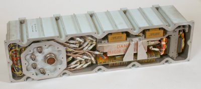
An Apollo-era TWTA, similar to the S-band and X-band power amps used on Voyager. Source: Ken Shirriff
On the transmit side, both the X-band and S-band transmitters use separate exciters and amplifiers, and again, multiple of each for redundancy. Although downlink is primarily via the X-band transmitter, either of the two S-band exciters can be fed into either of two different power amplifiers. A Solid State Amplifier (SSA) provides a selectable power output of either 6 W or 15 W to the feedhorn, while a separate traveling-wave tube amplifier (TWTA) provides either 6.5 W or 19 W. The dual X-band exciters, which use the S-band exciters as their frequency reference, use one of two dedicated TWTAs, each of which can send either 12 W or 18W to the high-gain antenna.
The redundancy built into the downlink side of the radio system would play a role in saving the primary mission on both spacecraft. In October of 1987, Voyager 1 suffered a failure in one of the X-band TWTAs. A little more than a year later, Voyager 2 experienced the same issue. Both spacecraft were able to switch to the other TWTA, allowing Voyager 1 to send back the famous “Family Portrait” of the Solar system including the Pale Blue Dot picture of Earth, and for Voyager 2 to send data back from its flyby of Neptune in 1989.
Slower and Slower
The radio systems on the Voyager systems were primarily designed to support the planetary flybys, and so were optimized to stream as much science data as possible back to the DSN. The close approaches to each of the outer planets meant each spacecraft accelerated dramatically during the flybys, right at the moment of maximum data production from the ten science instruments onboard. To avoid bottlenecks, each Voyager included a Digital Tape Recorder (DTR), which was essentially a fancy 8-track tape deck, to buffer science data for later downlink.
Also, the increasing distance to each Voyager has drastically decreased the bandwidth available to downlink science data. When the spacecraft made their first flybys of Jupiter, data streamed at a relatively peppy 115,200 bits per second. Now, with the spacecraft each approaching a full light-day away, data drips in at only 160 bps. Uplinked commands are even slower, a mere 16 bps, and are blasted across space from the DSN’s 70-meter dish antennas using 18 kW of power. The uplink path loss over the current 23 billion kilometer distance to Voyager 1 exceeds 200 dB; on the downlink side, the DSN telescopes have to dig a signal that has faded to the attowatt (10-18 W) range.
That the radio systems of Voyager 1 and Voyager 2 worked at all while they were still in the main part of their planetary mission is a technical achievement worth celebrating. The fact that both spacecraft are still communicating, despite the challenges of four decades in space and multiple system failures, is nearly a miracle.