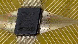
Hackaday regular [befinitiv] wrote into the tip line to let us know about a hack you might enjoy, wireless UART output from a bare STM32 microcontroller. Desiring the full printf debugging experience, but constrained both by available space and expense, [befinitiv] was inspired to improvise by a similar hack that used the STM32 to send Morse code over standard FM frequencies.
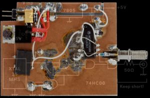
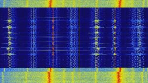
In this case, [befinitiv]’s solution is both more useful and slightly more legal, as the software uses the 27 MHz ISM band to blast out ASK modulated serial data through a simple wire antenna attached to one of the microcontroller’s pins. The broadcast can then be picked up by an RTL-SDR receiver and interpreted back into a stream of data by GNU Radio.
The software for the STM32 and the GNU Radio Companion graph are both available on Bitbucket. The blog post goes into some detail explaining how the transmitter works and what all the GNU Radio components are doing to claw the serial data back from the ether.
When I started working in a video production house in the early 1980s, it quickly became apparent that there was a lot of snobbery in terms of equipment. These were the days when the home video market was taking off; the Format War had been fought and won by VHS, and consumer-grade VCRs were flying off the shelves and into living rooms. Most of that gear was cheap stuff, built to a price point and destined to fail sooner rather than later, like most consumer gear. In our shop, surrounded by our Ikegami cameras and Sony 3/4″ tape decks, we derided this equipment as “ReggieVision” gear. We were young.
For me, one thing that set pro gear apart from the consumer stuff was the type of connectors it had on the back panel. If a VCR had only the bog-standard F-connectors like those found on cable TV boxes along with RCA jacks for video in and out, I knew it was junk. To impress me, it had to have BNC connectors; that was the hallmark of pro-grade gear.
I may have been snooty, but I wasn’t really wrong. A look at coaxial connectors in general and the design decisions that went into the now-familiar BNC connector offers some insight into why my snobbery was at least partially justified.
Keeping the Impedance
The connector that would eventually become known as the BNC connector when it was invented in the 1950s has its roots in two separate connectors developed in the 1930s and 1940s for the burgeoning radio and telephone industries. When it comes to wires and connectors for DC and low-frequency AC circuits, pretty much anything that will carry the current and provide a firm mechanical connection will do. But once a circuit is into the radio frequency range it’s a different story. At such frequencies coaxial cable is preferred for transmission line, and any connectors inserted into the line need to be engineered to minimize changes in impedance, which could cause reflection of the signal and generate standing waves that can cause damage.
Paul Neil, an electrical engineer who had been with the Bell Company since 1916, was well versed in RF systems. In the 1940s he identified a need for a coaxial connector capable of working well at microwave frequencies and designed the Type N connector. Like all coaxial connectors, it was designed to present as little change in the characteristic impedance of the feedline as possible by keeping the spacing between the center conductor connection and the outer shell as close to the feedline dimensions as possible. Neil’s connector had a female threaded outer shell on the plug that mated with male threads on the matching socket, and was designed to be weatherproof. The N connector took its name from Neil’s last initial and is still in use to this day.
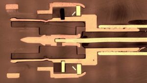
Type-C connector and a BNC, both male. Source: Wikipedia
Meanwhile, an engineer at Amphenol Corporation was working on his own design. Carl Concelman’s connector, similarly dubbed the Type C connector, used the same approach to reduce impedance changes in coaxial connections. However, he chose to make his connector quick-disconnect; rather than tediously screwing and unscrewing the outer shell, the C connector had a bayonet connection. The outer shell of the socket had lugs diametrically opposed on its outer surface. These lugs would mate with the long arm of L-shaped grooves machined into the inner surface of the outer shell on the plug. The shell would be rotated to move the lugs into the short arm of the groove, locking the two connectors together mechanically and electrically.385
Both the N and the C connectors enjoyed success in the marketplace, but neither was ideal. The N connector was slimmer in profile than the C but had all that pesky threading and unthreading to deal with; the C connector has that nice quick-disconnect but was bulky. In addition, neither connector was particularly easy to manufacture as each required some fairly fancy machining. With those shortcomings in mind, an engineer at the Hazeltine Electronics Corporation named Octavio Salati came up with his own design. It would have the bayonet locking feature of the C connector and the slimmer profile of the N connector. It used the same techniques as both connectors to minimize reflections due to inline impedance changes.
Salati’s connector was patented in 1951 with the unexciting name “Electrical Connector.” Unlike its predecessors, it would not be dubbed the “S-Connector” but, in a gentlemanly gesture, it was called the BNC, for “Bayonet Neil-Conselman.” To support the RF work for which it was originally designed, the connector had a 50-ohm characteristic impedance; later, a 75-ohm version was made for the television industry. The connector is usable up to around 11 GHz, although it’s not ideal past 4 GHz or so owing to the slots cut into the conductor for the outer shield, which start to radiate signals.
The BNC connector has seen widespread acceptance as a coaxial connector in industries far beyond its original target markets. From public service communications to scope probes to computer networking, Salati’s design, and by extension both Neil’s and Conselman’s, has delivered solid performance for the past sixty years.
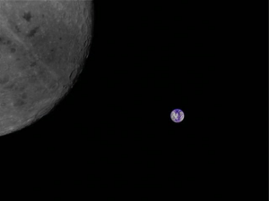
Ham radio operators bouncing signals off the moon have become old hat. But a ham radio transmitter on the Chinese Longjiang-2 satellite is orbiting the moon and has sent back pictures of the Earth and the dark side of the moon. The transceiver’s main purpose is to allow hams to downlink telemetry and relay messages via lunar orbit.
While the photo was received by the Dwingeloo radio telescope, reports are that other hams also picked up the signal. The entire affair has drawn in hams around the world. Some of the communications use a modulation scheme devised by [Joe Taylor, K1JT] who also happens to be a recipient of a Nobel prize for his work with pulsars. The Dwingeloo telescope has several ham radio operators including [PA3FXB] and [PE1CHQ].
You can find technical particulars about the satellite on its web page. There are also GNU Radio receivers and information about tracking. If you want to listen in, you’ll need some gear, but it looks very doable. The same page details several successful ham radio stations including those from [PY2SDR], [CD3NDC], [PY4ZBZ], [N6RFM], and many others. While the Dwingeloo telescope is a 25-meter dish, most of the stations have more conventional looking Yagi or helical antennas.
If your Mandarin is up to it, there is live telemetry on that page, too. You might have more luck with the pictures.
For working conventional satellites, you often need an agile antenna. We suspect the lunar orbiting satellite appears to move less, but you’ll have other problems with more noise and weak signals. Although hams have been bouncing signals off the moon for decades, they’ve only recently started bouncing them off airplanes.
AI is currently popular, so [Chirs Lam] figured he’d stimulate some interest in amateur radio by using it to pull call signs from radio signals processed using SDR. As you’ll see, the AI did just okay so [Chris] augmented it with an algorithm invented for gene sequencing.
His experiment was simple enough. He picked up a Baofeng handheld radio transceiver to transmit messages containing a call sign and some speech. He then used a 0.5 meter antenna to receive it and a little connecting hardware and a NooElec SDR dongle to get it into his laptop. There he used SDRSharp to process the messages and output a WAV file. He then passed that on to the AI, Google’s Cloud Speech-to-Text service, to convert it to text.
Despite speaking his words one at a time and making an effort to pronounce them clearly, the result wasn’t great. In his example, only the first two words of the call sign and actual message were correct. Perhaps if the AI had been trained on actual off-air conversations with background noise, it would have been done better. It’s not quite the same issue, but we’re reminded of those MIT researchers who fooled Google’s Inception image recognizer into thinking that a turtle was a gun.
Rather than train his own AI, [Chris’s] clever solution was to turn to the Smith-Waterman algorithm. This is the same algorithm used for finding similar nucleic acid sequences when analyzing genes. It allowed him to use a list of correct call signs to find the best match for what the AI did come up with. As you can see in the video below, it got the call signs right.
Dead-bug circuit building is not a pretty affair, but hey, function over form. We usually make them because we don’t have a copper circuit board available or the duty of making one at home is not worth the efforts and chemical stains.
[Robert Melville and Alaina G. Levine] bring to light a compromise for high-frequency prototypes which uses the typical FR4 blank circuit board, but no etching chemicals. The problem with high-frequency radio is that building a circuit on a breadboard will not work because there is too much added inductance and capacitance from the wiring that will wreak havoc on the whole circuit. The solution is not new, build your radio module on a circuit board by constructing “lands” over a conductive ground plane, where components can be isolated on the same unetched board.
All right, sometimes dead-bug circuits capture an aesthetic all their own, especially when they look like this and they do allow for a darned small package for one-off designs.


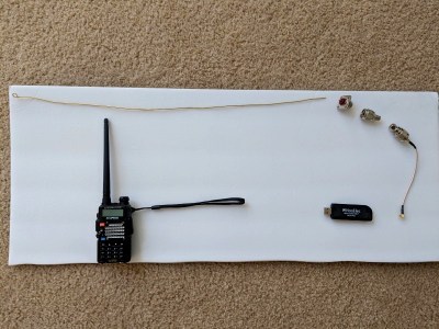 His experiment was simple enough. He picked up a Baofeng handheld radio transceiver to transmit messages containing a call sign and some speech. He then used a 0.5 meter antenna to receive it and a little connecting hardware and a NooElec