Op maandag 7 juli is een nieuwe remote ontvanger in gebruik genomen voor de 2 meter regiorepeater PI3ZLB. De nieuwe ontvanger staat op locatie bij PI1ZLB, in Maastricht-West (Daalhof). In de afgelopen periode zijn daarvoor een nieuwe multi-band antenne geplaatst voor 2 en 70, is de datalink naar de locatie verbeterd, en werd verouderde netwerk apparatuur vervangen.
De ontvanger is voorzien van een HA8ET 144Mhz contest preamplifier, met een ruisgetal van <0,6dB. Deze preamp heeft een IP3 van +40dBm, 60db demping voor de FM omroepband en 50dB demping op 70cm. De diplexer voegt daar nog eens 60dB aan toe op 70cm, bij een doorlaatdemping van minder dan 0,8dB.
Op basis van van de ontvangstrapporten van de 70cm repeater PI1ZLB, de antennehoogte van 124m boven N.A.P. en het vrije zicht op de wijde omgeving verwacht het repeater-team dat deze toevoeging de bereikbaarheid van de regio-reeater PI3ZLB in Maastricht en omgeving zal verbeteren.
De ingebruikname van de nieuwe ontvanger heeft geen invloed op de werking of het gebruik van de 70cm repeater PI1ZLB.
Om een goede dekking voor de repeater in het Zuid-Limburgse heuvelland te bereiken zijn, behalve een centrale ligging in Zuid-Limburg, de antennehoogte en storingsvrije omgeving belangrijke factoren. De zender in Hulsberg is weliswaar centraal gelegen, maar mist wat hoogte. De repeater is desondanks door de meeste gebruikers redelijk tot goed te ontvangen.
Voor mobiele gebruikers met laag vermogen, en gebruikers zonder buitenantenne kan het soms uitdagend zijn om over de repeater te komen. Om die reden zijn, verspreid over de regio, een aantal extra ontvangers toegevoegd:
Hulsberg – PI3ZLB
Brunssum – PA0EJH
Maastricht – PI1ZLB
Hulsberg – PE1RLN
Cadier en Keer – NL13866
TIP: Aan het aantal roger-piepjes na afloop van je uitzending kun je horen op welke ontvanger je het beste ontvanger werd, zie het lijstje hierboven.
We horen graag over je ervaringen met de bereikbaarheid van de repeaters PI3ZLB en PI1ZLB. Laat het ons weten op een clubavond.
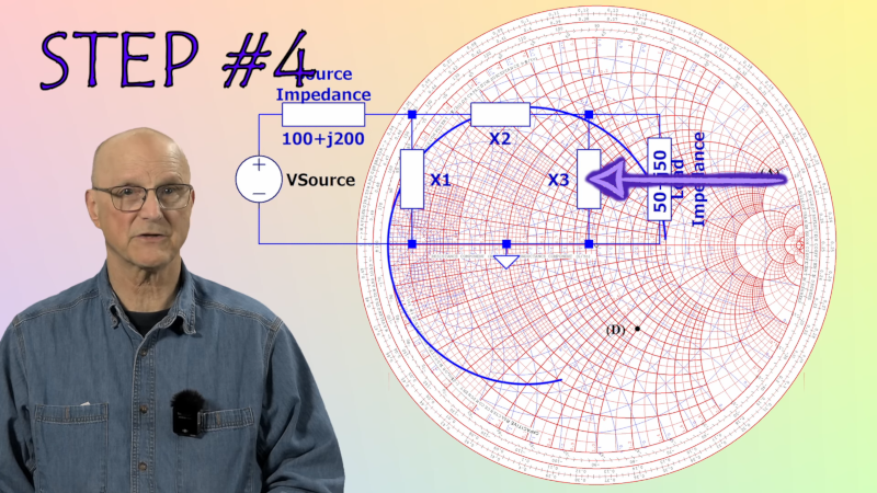
[Ralph] is excited about impedance matching, and why not? It is important to match the source and load impedance to get the most power out of a circuit. He’s got a whole series of videos about it. The latest? Matching using a PI network and the venerable Smith Chart.
We like that he makes each video self-contained. It does mean if you watch them all, you get some review, but that’s not a bad thing, really. He also does a great job of outlining simple concepts, such as what a complex conjugate is, that you might have forgotten.
Smith charts almost seem magical, but they are really sort of an analog computer. The color of the line and even the direction of an arrow make a difference, and [Ralph] explains it all very simply.
The example circuit is simple with a 50 MHz signal and a mismatched source and load. Using the steps and watching the examples will make it straightforward, even if you’ve never used a Smith Chart before.
The red lines plot impedance, and the blue lines show conductance and succeptance. Once everything is plotted, you have to find a path between two points on the chart. That Smith was a clever guy.
We looked at part 1 of this series earlier this year, so there are five more to watch since then. If your test gear leaves off the sign of your imaginary component, the Smith Chart can work around that for you.
I often ask people: What’s the most important thing you need to have a successful fishing trip? I get a lot of different answers about bait, equipment, and boats. Some people tell me beer. But the best answer, in my opinion, is fish. Without fish, you are sure to come home empty-handed.
On a recent visit to Bletchley Park, I thought about this and how it relates to World War II codebreaking. All the computers and smart people in the world won’t help you decode messages if you don’t already have the messages. So while Alan Turing and the codebreakers at Bletchley are well-known, at least in our circles, fewer people know about Arkley View.
The problem was apparent to the British. The Axis powers were sending lots of radio traffic. It would take a literal army of radio operators to record it all. Colonel Adrian Simpson sent a report to the director of MI5 in 1938 explaining that the three listening stations were not enough. The proposal was to build a network of volunteers to handle radio traffic interception.
That was the start of the Radio Security Service (RSS), which started operating out of some unused cells at a prison in London. The volunteers? Experienced ham radio operators who used their own equipment, at first, with the particular goal of intercepting transmissions from enemy agents on home soil.
At the start of the war, ham operators had their transmitters impounded. However, they still had their receivers and, of course, could all read Morse code. Further, they were probably accustomed to pulling out Morse code messages under challenging radio conditions.
Over time, this volunteer army of hams would swell to about 1,500 members. The RSS also supplied some radio gear to help in the task. MI5 checked each potential member, and the local police would visit to ensure the applicant was trustworthy. Keep in mind that radio intercepts were also done by servicemen and women (especially women) although many of them were engaged in reporting on voice communication or military communications.
Early Days
The VIs (voluntary interceptors) were asked to record any station they couldn’t identify and submit a log that included the messages to the RSS.
The hams of the RSS noticed that there were German signals that used standard ham radio codes (like Q signals and the prosign 73). However, these transmissions also used five-letter code groups, a practice forbidden to hams.
Thanks to a double agent, the RSS was able to decode the messages that were between agents in Europe and their Abwehr handlers back in Germany (the Abwehr was the German Secret Service) as well as Abwehr offices in foreign cities. Later messages contained Enigma-coded groups, as well.
Between the RSS team’s growth and the fear of bombing, the prison was traded for Arkley View, a large house near Barnet, north of London. Encoded messages went to Bletchley and, from there, to others up to Churchill. Soon, the RSS had orders to concentrate on the Abwehr and their SS rivals, the Sicherheitsdienst.
Change in Management
In 1941, MI6 decided that since the RSS was dealing with foreign radio traffic, they should be in charge, and thus RSS became SCU3 (Special Communications Unit 3).
There was fear that some operators might be taken away for normal military service, so some operators were inducted into the Army — sort of. They were put in uniform as part of the Royal Corps of Signals, but not required to do very much you’d expect from an Army recruit.
Those who worked at Arkley View would process logs from VIs and other radio operators to classify them and correlate them in cases where there were multiple logs. One operator might miss a few characters that could be found in a different log, for example.
It soon became clear that the RSS needed full-time monitoring, so they built a number of Y stations with two National HRO receivers from America at each listening position. There were also direction-finding stations built in various locations to attempt to identify where a remote transmitter was.
Many of the direction finding operators came from VIs. The stations typically had four antennas in a directional array. When one of the central stations (the Y stations) picked up a signal, they would call direction finding stations using dedicated phone lines and send them the signal.
The operator would hear the phone signal in one ear and the radio signal in the other. Then, they would change the antenna pattern electrically until the signal went quiet, indicating the antenna was electrically pointing away from the signals.
The DF operator would hear this signal in one earpiece. They would then tune their radio receiver to the right frequency and match the signal from the main station in one ear to the signal from their receiver in the other ear. This made sure they were measuring the correct signal among the various other noise and interference. The DF operator would then take a bearing by rotating the dial on their radiogoniometer until the signal faded out. That indicated the antenna was pointing the wrong way which means you could deduce which way it should be pointing.
The central station could plot lines from three direction finding stations and tell the source of a transmission. Sort of. It wasn’t incredibly accurate, but it did help differentiate signals from different transmitters. Later, other types of direction-finding gear saw service, but the idea was still the same.
Interesting VIs
Most of the VIs, like most hams at the time, were men. But there were a few women, including Helena Crawley. She was encouraged to marry her husband Leslie, another VI, so they could be relocated to Orkney to copy radio traffic from Norway.
In 1941, a single VI was able to record an important message of 4,429 characters. He was bedridden from a landmine injury during the Great War. He operated from bed using mirrors and special control extensions. For his work, he receive the British Empire Medal and a personal letter of gratitude from Churchill.
Results
Because of the intercepts of the German spy agency’s communications, many potential German agents were known before they arrived in the UK. Of about 120 agents arriving, almost 30 were turned into double agents. Others were arrested and, possibly, executed.
By the end of the war, the RSS had decoded around a quarter of a million intercepts. It was very smart of MI5 to realize that it could leverage a large number of trained radio operators both to cover the country with receivers and to free up military stations for other uses.
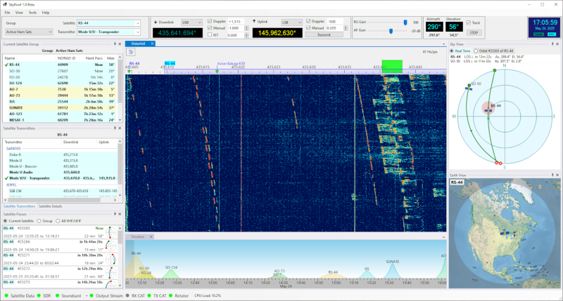
Communicating with space-based ham radio satellites might sound like it’s something that takes a lot of money, but in reality it’s one of the more accessible aspects of the hobby. Generally all that’s needed is a five-watt handheld transceiver and a directional antenna. Like most things in the ham radio world, though, it takes a certain amount of skill which can’t be easily purchased. Most hams using satellites like these will rely on some software to help track them, which is where this new program from [Alex Shovkoplyas] comes in.
The open source application is called SkyRoof and provides a number of layers of information about satellites aggregated into a single information feed. A waterfall diagram is central to the display, with not only the satellite communications shown on the plot but information about the satellites themselves. From there the user can choose between a number of other layers of information about the satellites including their current paths, future path prediction, and a few different ways of displaying all of this information. The software also interfaces with radios via CAT control, and can even automatically correct for the Doppler shift that is so often found in satellite radio communications.
For any ham actively engaged in satellite tracking or space-based repeater communications, this tool is certainly worth trying out. Unfortunately, it’s only available for Windows currently. For those not looking to operate under Microsoft’s thumb, projects such as DragonOS do a good job of collecting up the must-have Linux programs for hams and other radio enthusiasts.
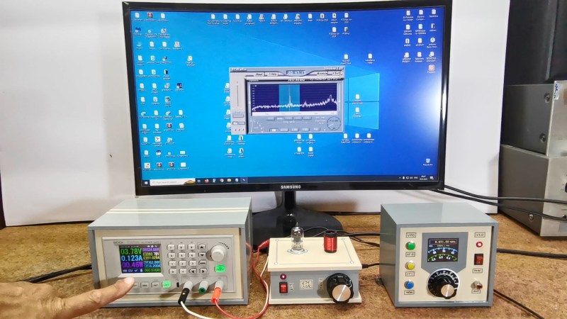
Software Defined Radio (SDR) is the big thing these days, and why not? A single computer can get rid of a room full of boat anchors, and give you better signal discrimination than all but the best kit. Any SDR project needs an RF receiver, and in this project [mircemk] used a single 6J1 vaccum tube to produce an SSB SDR that combines the best of old and new.
Single-tube radios are a classic hack, and where a lot of hams got started back in the day, but there is a reason more complicated circuits tend to be used. On the other hand, if you can throw a PC worth of signal processing at the output, it looks like you can get a very sensitive and selective single-sideband (SSB) receiver.
The 6J1 tube is convenient, since it can run on only 6 V (or down to 3.7 as [mircemk] demonstrates). Here it is used as a mixer, with the oscillator signal injected via the screen grid. Aside from that, the simple circuit consists of a receiving coil, a few resistors and a variable capacitor. How well does it work? Quite well, when paired with a PC; you can judge for yourself in the video embedded below.
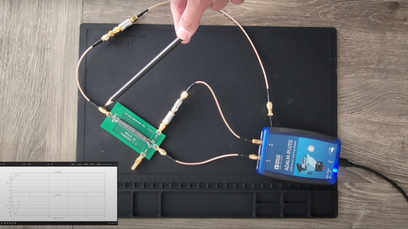
Usually when we see a project using a software-defined radio (SDR), the SDR’s inputs and outputs are connected to antennae, but [FromConceptToCircuit]’s project connected an ADALM-Pluto SDR to an RF bridge and a few passive components to make a surprisingly effective network analyzer (part two of the video).
The network analyzer measures two properties of the circuit to which it is connected: return loss (S11) and insertion gain or loss (S21). To measure S21, the SDR feeds a series of tones to the device under test, and reads the device’s output from one of the SDR’s inputs. By comparing the amplitude of the input to the device’s output, a Python program can calculate S21 over the range of tested frequencies. To find S11, [FromConceptToCircuit] put an RF bridge in line with the device being tested and connected the bridge’s output to the SDR’s second input. This allowed the program to calculate the device’s impedance, and from that S11.
The RF bridge and other components introduce some inaccuracies to the measurements, so before making any other measurements, the system is calibrated with both a through connection and an open circuit in place of the tested device. The RF bridge’s directivity was the biggest limiting factor; transfer back from the bridge’s output line caused the reflection under load to exceed the reflection of an open circuit in some frequency ranges, at which point the analyzer couldn’t accurately operate.
[FromConceptToCircuit] was eventually able to make measurements throughout most of the 0.1-3 GHz range with a dynamic range of at least 10 dB, and expects a more directive RF bridge to give even better results. If you’d like to repeat the experiment, he’s made his Python program available on GitHub.
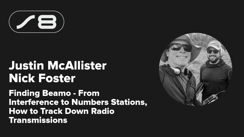
You turn the dial on your radio, and hear a powerful source of interference crackle in over the baseline noise. You’re interested as to where it might be coming from. You’re receiving it well, and the signal strength is strong, but is that because it’s close or just particularly powerful? What could it be? How would you even go about tracking it down?
When it comes to hunting down radio transmissions, Justin McAllister and Nick Foster have a great deal of experience in this regard. They came down to the 2024 Hackaday Superconference to show us how it’s done.
Transmissions From Where?
Nick Foster opens the talk by discussing how the first job is often to figure out what you’re seeing when you pick up a radio transmission. “The moral of this talk is that your hardware is always lying to you,” says Nick. “In this talk, we’re going to show you how your radio lies to you, what you can do about it, and if your hardware is not lying to you, what is that real station that you’re looking at?” It can be difficult to tease out the truth of what the radio might seem to be picking up. “How do we determine what a signal actually is?” he asks. “Is it a real signal that we’re looking at which is being transmitted deliberately from somebody else, or is it interference from a bad power supply, or is it a birdie—a signal that’s created entirely within my own radio that doesn’t exist at all?”
There are common tools used to perform this work of identifying just what the radio is actually picking up and where it’s coming from. Justin goes over some of the typical hardware, noting that the RX-888 is a popular choice for software-defined radio that can be tuned across HF, VHF, and UHF bands. It’s highly flexible, and it’s affordable to boot, as is the Web-888 which can be accessed conveniently over a web browser. Other common SDRs are useful, too, as are a variety of filters that can aid with more precise investigations.
Justin demonstrates an errant radio emission from the brushed motor in his furnace, noting how it varies in bandwidth—a surefire tell versus intentional radio transmissions.
Establishing a grounding in reality is key, Justin steps up to explain. “We turn our SDR on, we stick [on] the little antenna that comes with it, and we start looking at something,” says Justin. “Are the signals that we see there actually real?” He notes that there are some basics to consider right off the bat. “One key point to make is that nobody makes money or has good communication using an unmodulated carrier,” he points out. “If you just see a tone somewhere, it might be real, but there’s a good chance that it’s not.”
It’s perhaps more likely unintentional radiation, noise, or something generated inside the hardware itself on your end. It’s also worth looking at whether you’re looking at a fixed frequency or a changing frequency to pin things down further. Gesturing to a spectrogram, he notes that the long, persistent lines on the spectrogram are usually clues to more intentional transmissions. Intermittent squiggles are more often unintentional. Justin points at some that he puts down to the emissions from arc welders, sparking away as they do, and gives an example of what emissions from typical switching power supplies look like.
There are other hints to look out for, too. Real human-made signals tend to have some logic to them. Justin notes that real signals usually make “efficient” use of spectrum without big gaps or pointless repetition. It’s also possible to make judgement calls as to whether a given signal makes sense for the band it appears to be transmitted in. Schedule can be a tell, too—if a signal always pops up when your neighbor gets home at 6 PM, it might just be coming from their garage door remote. Justin notes a useful technique for hunting down possible nearby emitters—”Flipping on and off switches is a real good way of figuring out—is it close to me or not?”
SDRs are hugely flexible, but they also have very open front-ends that can lead to some confusing output.
Nick follows up by discussing the tendency of sampling radios to show up unique bizarre transmissions that aren’t apparent on an analog receiver. “One of the curses of the RTL-SDR is actually one of its strengths… it has a completely wide open front end,” notes Nick. “Its ADC which is sampling and capturing the RF has basically nothing except an amplifier in between it and whatever crud you’re putting into it.” This provides great sensitivity and frequency agility, but there’s a catch—”It will happily eat up and spit out lots of horrible stuff,” says Nick. He goes on to explain various ways such an SDR might lie to the user. A single signal might start popping up all over the frequency band, or interfere with other signals coming in from the antenna. He also highlights a great sanity check for hunting down birdies—”If it’s always there, if it’s unchanging, if you unplug your antenna and you still hear it—it’s probably generated in your radio!”
The rest of the talk covers locating transmissions—are they in your house, in the local community, or from even farther afield? It explores the technique of multilateration, where synchronized receivers and maths are used to measure the time differences seen in the signal at each point to determine exactly where a transmission is coming from. The talk also goes over common sources of noise in residential settings—cheap PWM LED lights, or knock-off laptop chargers being a prime example in Nick’s experience. There’s also a discussion of how the noise floor has shifted up a long way compared to 50 years ago, now that the world is full of so many more noise-emitting appliances.
Ultimately, the duo of Justin and Nick brought us a great pun-filled talk on sleuthing for the true source of radio transmissions. If you’ve ever wondered about how to track down some mystery transmitter, you would do well to watch and learn from the techniques explored within
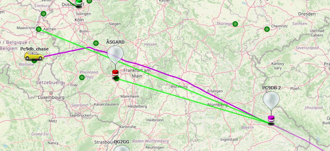
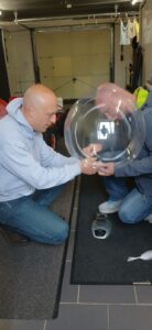
Op donderdag 29 mei liet Velddaggroep Zuid-Limburg een weerballon op vanuit Dochamps (B). Mark PC9DB en Thijs PE1RLN lieten al eerder ballonnen op om te volgen, tijdens deze velddag krijgt de rest ook eens te zien hoe je dit fenomeen aanpakt. Gewapend met een fles helium en een precieze weegschaal wordt de ballon gevuld en voorzien van z’n payload. Deze bestaat uit een gebruikte weersonde met speciale lithium batterijen die opnieuw is geprogrammeerd om in de 70cm band met het Horus protocol z’n telemetrie uit te zenden.
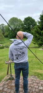
Het miezert een beetje, niet ideaal maar we gokken het erop. De ballon wordt opgelaten en gelukkig maakt hij snel hoogte en begint z’n reis over de wereld.
Aanvankelijk vertrok de ballon weliswaar voortvarend maar door de regen werd de ballon te zwaar en begon deze te dalen… Er wordt overlegd of we de ballon gaan zoeken of het erbij laten.
Mark, Thijs en Tony gingen met de auto er achteraan, richting de laatst ontvangen positie. Maar ja, dat is niet per se de locatie waar de ballon uiteindelijk is geland dus dan is goede raad duur… Met portofoon en laptop in de hand dan maar door het bos het veld in, in de hoop op een signaal:
Het was gelukkig goed weer waardoor onze avonturiers boven op de heuvel konden komen alwaar ze het signaal opnieuw oppikten! De ballon moest dus in de buurt zijn dus werd de portofoon weer op de laptop aangesloten en werd gewacht op de volgende positie.
Gotcha!
Maar ja, dat was natuurlijk niet op de gewenste plek dus de woudlopers moesten door een aantal velden door anderhalve meter hoog gras om zodoende in de buurt te komen van de ballon.
Maar goed, het was niet te warm en een gezonde wandeling kon geen kwaad.
Door metershoog gras, pas ingezaaid gewas, door kuddes koeien richting het bosje waar de ballon zou moeten zijn. Hoge bomen… Oei. Op Google Maps leek het nog een laag bosje maar dit zijn stevige bomen en als de ballon boven in de boom hangt, zijn we de sjaak.
Maar niet gewanhoopt, het team komt dichterbij en eindelijk zijn we op dezelfde positie aangekomen waar de ballon telkens z’n positie van opgeeft. Maar ja, ga maar zoeken. Turend in de lucht naar de transparante ballon vindt Mark uiteindelijk ons verloren experiment:
In een klein boompje, je kunt er zo bij! Dat is nog eens geluk hebben. Na de ballon uit de boom gevist te hebben zonder lekkage wordt gecontroleerd of deze nog wel wil stijgen: dan moeten we ‘m eerst afdrogen natuurlijk want hij was niet voor niets omlaag gekomen. De ballon is kletsnat van de regendruppels en met een netto lift van ~10 gram zijn een paar druppels al gauw net iets teveel.
We zoeken het hogerop om de ballon opnieuw het luchtruim te laten opzoeken. Het waait flink maar dat mag de pret niet drukken.
Zo. En nu weer dat hele takke eind terug wandelen in de hoop dat de ballon deze keer een langere reis zal maken. Terug aangekomen op de velddag blijkt dat de ballon buiten het bereik is geraakt van de eigen ontvanger, dat kan van alles betekenen… De hele avond lijkt het erop dat de ballon wederom ergens is terecht gekomen…
’s Ochtends blijkt echter dat de ballon wel degelijk z’n reis heeft vervolgd! Hij zweeft richting Oostenrijk en we blijven onze vriend volgen via diverse ontvangers:
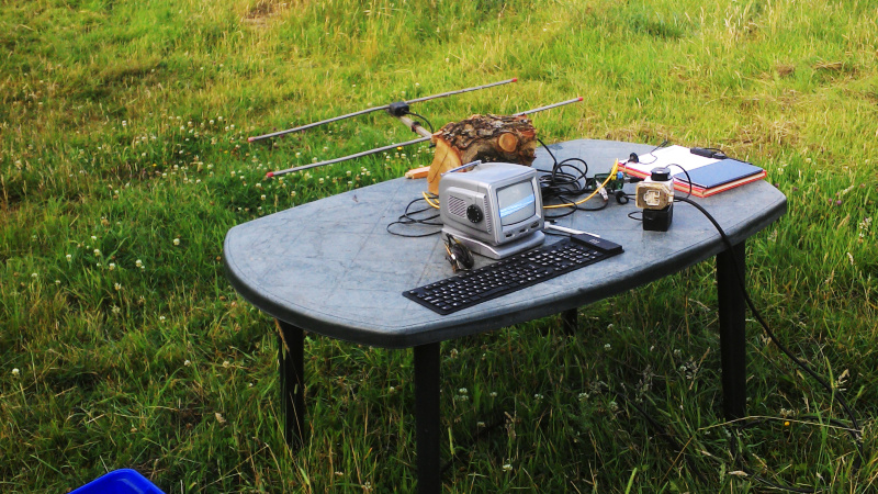
The ARRL used to have a requirement that any antenna advertised in their publications had to have real-world measurements accompanying it, to back up any claims of extravagant performance. I’m told that nowadays they will accept computer simulations instead, but it remains true that knowing what your antenna does rather than just thinking you know what it does gives you an advantage. I was reminded of this by a recent write-up in which the performance of a mylar sheet as a ground plane was tested at full power with a field strength meter, because about a decade ago I set out to characterise an antenna using real-world measurements and readily available equipment. I was in a sense field testing it, so of course the first step of the process was to find a field. A real one, with cows.
Walking Round And Round A Field In The Name Of Science
A very low-tech way to make field recordings.
The process I was intending to follow was simple enough. Set up the antenna in the middle of the field, have it transmit some RF, and measure the signal strength at points along a series of radial lines away from it I’d end up with a spreadsheet, from which I could make a radial plot that would I hoped, give me a diagram showing its performance. It’s a rough and ready methodology, but given a field and a sunny afternoon, not one that should be too difficult.
I was more interested in the process than the antenna, so I picked up my trusty HB9CV two-element 144MHz antenna that I’ve stood and pointed at the ISS many times to catch SSTV transmissions. It’s made from two phased half-wave radiators, but it can be seen as something similar to a two-element Yagi array. I ran a long mains lead oput to a plastic garden table with the HB9CV attached, and set up a Raspberry Pi whose clock would produce the RF.
My receiver would be an Android tablet with an RTL-SDR receiver. That’s pretty sensitive for this purpose, so my transmitter would have to be extremely low powered. Ideally I would want no significant RF to make it beyond the boundary of the field, so I gave the Pi a resistive attenuator network designed to give an output of around 0.03 mW, or 30 μW. A quick bit of code to send my callsign as CW periodically to satisfy my licence conditions, and I was off with the tablet and a pen and paper. Walking round the field in a polar grid wasn’t as easy as it might seem, but I had a very long tape measure to help me.
A Lot Of Work To Tell Me What I Already Knew
And lo! for I have proven an HB9CV to be directional!
I ended up with a page of figures, and then a spreadsheet which I’m amused to still find in the depths of my project folder. It contains a table of angles of incidence to the antenna versus metres from the antenna, and the data points are the figure in (uncalibrated) mV that the SDR gave me for the carrier at that point. The resulting polar plot shows the performace of the antenna at each angle, and unsurprisingly I proved to myself that a HB9CV is indeed a directional antenna.
My experiment was in itself not of much use other than to prove to myself I could characterise an antenna with extremely basic equipment. But then again it’s possible that in times past this might have been a much more difficult task, so knowing I can do it at all is an interesting conclusion.
The world’s militaries have always been at the forefront of communications technology. From trumpets and drums to signal flags and semaphores, anything that allows a military commander to relay orders to troops in the field quickly or call for reinforcements was quickly seized upon and optimized. So once radio was invented, it’s little wonder how quickly military commanders capitalized on it for field communications.
Radiotelegraph systems began showing up as early as the First World War, but World War II was the first real radio war, with every belligerent taking full advantage of the latest radio technology. Chief among these developments was the ability of signals in the high-frequency (HF) bands to reflect off the ionosphere and propagate around the world, an important capability when prosecuting a global war.
But not long after, in the less kinetic but equally dangerous Cold War period, military planners began to see the need to move more information around than HF radio could support while still being able to do it over the horizon. What they needed was the higher bandwidth of the higher frequencies, but to somehow bend the signals around the curvature of the Earth. What they came up with was a fascinating application of practical physics: meteor burst communications.
Blame It on Shannon
In practical terms, a radio signal that can carry enough information to be useful for digital communications while still being able to propagate long distances is a bit of a paradox. You can thank Claude Shannon for that, after he developed the idea of channel capacity from the earlier work of Harry Nyquist and Ralph Hartley. The resulting Hartley-Shannon Theorem states that the bit rate of a channel in a noisy environment is directly related to the bandwidth of the channel. In other words, the more data you want to stuff down a channel, the higher the frequency needs to be.
Unfortunately, that runs afoul of the physics of ionospheric propagation. Thanks to the physics of the interaction between radio waves and the charged particles between about 50 km and 600 km above the ground, the maximum frequency that can be reflected back toward the ground is about 30 MHz, which is the upper end of the HF band. Beyond that is the very-high frequency (VHF) band from 30 MHz to 300 MHz, which has enough bandwidth for an effective data channel but to which the ionosphere is essentially transparent.
Luckily, the ionosphere isn’t the only thing capable of redirecting radio waves. Back in the 1920s, Japanese physicist Hantaro Nagaoka observed that the ionospheric propagation of shortwave radio signals would change a bit during periods of high meteoric activity. That discovery largely remained dormant until after World War II, when researchers picked up on Nagoka’s work and looked into the mechanism behind his observations.
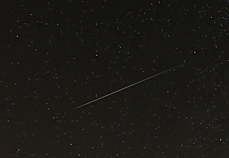
Every day, the Earth sweeps up a huge number of meteoroids; estimates range from a million to ten billion. Most of those are very small, on the order of a few nanograms, with a few good-sized chunks in the tens of kilograms range mixed in. But the ones that end up being most interesting for communications purposes are the particles in the milligram range, in part because there are about 100 million such collisions on average every day, but also because they tend to vaporize in the E-level of the ionosphere, between 80 and 120 km above the surface. The air at that altitude is dense enough to turn the incoming cosmic debris into a long, skinny trail of ions, but thin enough that the free electrons take a while to recombine into neutral atoms. It’s a short time — anywhere between 500 milliseconds to a few seconds — but it’s long enough to be useful.
A meteor trail from the annual Perseid shower, which peaks in early August. This is probably a bit larger than the optimum for MBC, but beautiful nonetheless. Source: John Flannery, CC BY-ND 2.0.
The other aspect of meteor trails formed at these altitudes that makes them useful for communications is their relative reflectivity. The E-layer of the ionosphere normally has on the order of 107 electrons per cubic meter, a density that tends to refract radio waves below about 20 MHz. But meteor trails at this altitude can have densities as high as 1011 to 1012 electrons/m3. This makes the trails highly reflective to radio waves, especially at the higher frequencies of the VHF band.
In addition to the short-lived nature of meteor trails, daily and seasonal variations in the number of meteors complicate their utility for communications. The rotation of the Earth on its axis accounts for the diurnal variation, which tends to peak around dawn local time every day as the planet’s rotation and orbit are going in the same direction and the number of collisions increases. Seasonal variations occur because of the tilt of Earth’s axis relative to the plane of the ecliptic, where most meteoroids are concentrated. More collisions occur when the Earth’s axis is pointed in the direction of travel around the Sun, which is the second half of the year for the northern hemisphere.
Learning to Burst
Building a practical system that leverages these highly reflective but short-lived and variable mirrors in the sky isn’t easy, as shown by several post-war experimental systems. The first of these was attempted by the National Bureau of Standards in 1951. They set up a system between Cedar Rapids, Iowa, and Sterling, Virginia, a path length of about 1250 km. Originally built to study propagation phenomena such as forward scatter and sporadic E, the researchers noticed significant effects on their tests by meteor trails. This made them switch their focus to meteor trails, which caught the attention of the US Air Force. They were in the market for a four-channel continuous teletype link to their base in Thule, Greenland. They got it, but only just barely, thanks to the limited technology of the time. The NBS system also used the Iowa to Virginia system to study higher data rates by pointing highly directional rhombic antennas at each end of the connection at the same small patch of sky. They managed a whopping data rate of 3,200 bits per second with this system, but only for the second or so that a meteor trail happened to appear.
The successes and failures of the NBS system made it clear that a useful system based on meteor trails would need to operate in burst mode, to jam data through the link for as long as it existed and wait for the next one. The NBS tested a burst-mode system in 1958 that used the 50-MHz band and offered a full-duplex link at 2,400 bits per second. The system used magnetic tape loops to buffer data and transmitters at both ends of the link that operated continually to probe for a path. Whenever the receiver at one end detected a sufficiently strong probe signal from the other end, the transmitter would start sending data. The Canadians got in on the MBC action with their JANET system, which had a similar dedicated probing channel and tape buffer. In 1954 they established a full-duplex teletype link between Ottawa and Nova Scotia at 1,300 bits per second with an error rate of only 1.5%
In the late 1950s, Hughes developed a single-channel air-to-ground MBC system. This was a significant development since not only had the equipment gotten small enough to install on an airplane but also because it really refined the burst-mode technology. The ground stations in the Hughes system periodically transmitted a 100-bit interrogation signal to probe for a path to the aircraft. The receiver on the ground listened for an acknowledgement from the plane, which turned the channel around and allowed the airborne transmitter to send a 100-bit data burst. The system managed a respectable 2,400 bps data rate, but suffered greatly from ground-based interference for TV stations and automotive ignition noise.
The SHAPE of Things to Come
Supreme HQ Allied Powers Europe (SHAPE), NATO’s European headquarters in the mid-60s. The COMET meteor-bounce system kept NATO commanders in touch with member-nation HQs via teletype. Source: NATO
The first major MBC system fielded during the Cold War was the Communications by Meteor Trails system, or COMET. It was used by the North Atlantic Treaty Organization (NATO) to link its far-flung outposts in member nations with Supreme Headquarters Allied Powers Europe, or SHAPE, located in Belgium. COMET took cues from the Hughes system, especially its error detection and correction scheme. COMET was a robust and effective MBC system that provided between four and eight teletype circuits depending on daily and seasonal conditions, each handling 60 words per minute.
COMET was in continuous use from the mid-1960s until well after the official end of the Cold War. By that point, secure satellite communications were nowhere near as prohibitively expensive as they had been at the beginning of the Space Age, and MBC systems became less critical to NATO. They weren’t retired, though, and COMET actually still exists, although rebranded as “Compact Over-the-Horizon Mobile Expeditionary Terminal.” These man-portable systems don’t use MBC; rather, they use high-power UHF and microwave transmitters to scatter signals off the troposphere. A small amount of the signal is reflected back to the ground, where high-gain antennas pick up the vanishingly weak signals.
Although not directly related to Cold War communications, it’s worth noting that there was a very successful MBC system fielded in the civilian space in the United States: SNOTEL. We’ve covered this system in some depth already, but briefly, it’s a network of stations in the western part of the USA with the critical job of monitoring the snowpack. A commercial MBC system connected the solar-powered monitoring stations, often in remote and rugged locations, to two different central bases. Taking advantage of diurnal meteor variations, each morning the master station would send a polling signal out to every remote, which would then send back the previous day’s data once a return path was opened. The system could collect data from 180 remote sites in just 20 minutes. It operated successfully from the mid-1970s until just recently, when pervasive cell technology and cheap satellite modems made the system obsolete.


 Op donderdag 29 mei liet Velddaggroep Zuid-Limburg een weerballon op vanuit Dochamps (B). Mark PC9DB en Thijs PE1RLN lieten al eerder ballonnen op om te volgen, tijdens deze velddag krijgt de rest ook eens te zien hoe je dit fenomeen aanpakt. Gewapend met een fles helium en een precieze weegschaal wordt de ballon gevuld en voorzien van z’n payload. Deze bestaat uit een gebruikte weersonde met speciale lithium batterijen die opnieuw is geprogrammeerd om in de 70cm band met het Horus protocol z’n telemetrie uit te zenden.
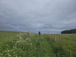 Het was gelukkig goed weer waardoor onze avonturiers boven op de heuvel konden komen alwaar ze het signaal opnieuw oppikten! De ballon moest dus in de buurt zijn dus werd de portofoon weer op de laptop aangesloten en werd gewacht op de volgende positie.
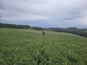 Maar goed, het was niet te warm en een gezonde wandeling kon geen kwaad.
 In een klein boompje, je kunt er zo bij! Dat is nog eens geluk hebben. Na de ballon uit de boom gevist te hebben zonder lekkage wordt gecontroleerd of deze nog wel wil stijgen: dan moeten we ‘m eerst afdrogen natuurlijk want hij was niet voor niets omlaag gekomen. De ballon is kletsnat van de regendruppels en met een netto lift van ~10 gram zijn een paar druppels al gauw net iets teveel.
 Zo. En nu weer dat hele takke eind terug wandelen in de hoop dat de ballon deze keer een langere reis zal maken. Terug aangekomen op de velddag blijkt dat de ballon buiten het bereik is geraakt van de eigen ontvanger, dat kan van alles betekenen… De hele avond lijkt het erop dat de ballon wederom ergens is terecht gekomen…