Cavity Filters, The Black Art You Have A Chance Of Pursuing

A tuned circuit formed by a capacitor and an inductor is a familiar enough circuit, and it’s understood that it will resonate at a particular frequency. As that frequency increases, so the size of the capacitor and inductor decrease, and there comes a point at which they can become the characteristic capacitance and inductance of a transmission line. These tuned circuits can be placed in an enclosure, at which they can be designed for an extremely high Q factor, a measure of quality, and thus a very narrow resonant point. They are frequently used as filters for that reason, and [Fesz] is here with a video explaining some of their operation and configurations.

Some of the mathematics behind RF design can be enough to faze any engineer, but he manages to steer a path away from that rabbit hole and explain cavity filters in a way that’s very accessible. We learn how to look at tuned circuits as transmission lines, and the properties of the various different coupling methods. Above all it reveals that making tuned cavities is within reach.

They’re a little rare these days, but there was a time when almost every TV set contained a set of these cavities which were ready-made for experimentation.


Hacking A Quansheng Handheld To Transmit Digital Modes

Have you ever thought about getting into digital modes on the ham bands? As it turns out, you can get involved using the affordable and popular Quansheng UV-K6 — if you’re game to modify it, that is. It’s perfectly achievable using the custom Mobilinkd firmware, the brainchild of one [Rob Riggs].

In order to efficiently transmit digital modes, it’s necessary to make some hardware changes as well. Low frequencies must be allowed to pass in through the MIC input, and to pass out through the audio output. These are normally filtered out for efficient transmission of speech, but these filters mess up digital transmissions something fierce.  This is achieved by messing about with some capacitors and bodge wires. Then, one can flash the firmware using a programming cable.

With the mods achieved, the UV-K6 can be used for transmitting in various digital modes, like M17 4-FSK. The firmware has several benefits, not least of which is cutting turnaround time. This is the time the radio takes to switch between transmitting and receiving, and slashing it is a big boost for achieving efficient digital communication. While the stock firmware has an excruciating slow turnaround of 378 ms, the Mobilinkd firmware takes just 79 ms.

Further gains may be possible in future, too. Bypassing the audio amplifier could be particularly fruitful, as it’s largely in the way of the digital signal stream.

Quansheng’s radios are popular targets for modification, and are well documented at this point.

Bijeenkomst voortaan op WOENSDAG

Vanaf 26 juni vinden de bijeenkomsten plaats op WOENSDAG vanaf 20:00 uur in Het Volkshuis te Heerlen. Tot die tijd zullen er op maandagavond geen bijeenkomsten plaatsvinden.

Onlangs is Het Volkshuis gewisseld van eigenaar. We zijn bijna twee jaar lang gastvrij ontvangen door Corina en Michael maar helaas hebben zij door omstandigheden hun horeca moeten overdragen. De nieuwe eigenaar, Boeike genaamd, is bijna elke dag geopend maar jammer genoeg niet op de maandag waardoor wij wederom moeten schuiven. In onderling overleg en op basis van de enquête die we een tijd geleden uitstuurden, zullen de bijeenkomsten daarom op woensdagavond plaatsvinden.

Tot woensdag!

Ham Busts The Myth Of Ground

Everyone who deals with electronics knows that grounding is important. Your house has a copper rod in the ground. But [Kristen K6WX] has news: the idea of ground is kind of a myth. She explained at a talk at the recent ARRL National Convention, and if you didn’t make it, you can watch it in the video below.

The problem is analogous to finding something that is standing still. You really can only talk about something standing still relative to something else. Sure, you might be standing still outside a building, but seen from the moon, you and the building are spinning around at about one revolution per day. If you were sitting on the sun and not burning up, you’d see lots of motion of everything, and, of course, the sun itself is moving in the right frame of reference.


So what’s ground? Just a common reference between two things. [Kristen] gets into RF grounds, DC grounds, and phasors. If you’ve ever wanted to ground your antenna or deal with RF interference, you’ll find a lot of information in this 45-minute video.

The name ground is, perhaps, unfortunate. You do want earth grounding for lightning protection, but what most of us think of as ground is just a convention. Need a -9V battery? Just reverse your meter leads, and there you go.

Getting a good common reference can be maddening. We’ve looked at way too many ground loops before.


Passive Diplexer Makes One Antenna Act Like Two

Stay in the amateur radio hobby long enough and you might end up with quite a collection of antennas. With privileges that almost extend from DC to daylight, one antenna will rarely do everything, and pretty soon your roof starts to get hard to see through the forest of antennas. It may be hell on curb appeal, but what’s a ham to do?

One answer could be making one antenna do the work of two, as [Guido] did with this diplexer for dual APRS setups. Automatic Packet Reporting System is a packet radio system used by hams to transmit telemetry and other low-bandwidth digital data. It’s most closely associated with the 2-meter ham band, but [Guido] has both 2-meter (144.8-MHz) and 70-cm LoRa (433.775-MHz) APRS IGates, or Internet gateway receivers. His goal was to use a single broadband discone antenna for both APRS receivers, and this would require sorting the proper signals from the antenna to the proper receiver with a diplexer.

Note that [Guido] refers to his design as a “duplexer,” which is a device to isolate and protect a receiver from a transmitter when they share the same antenna — very similar to a diplexer but different. His diplexer is basically a pair of filters in parallel — a high-pass filter tuned to just below the 70-cm band, and a low-pass filter tuned just above the top of the 2-m band. The filters were designed using a handy online tool and simulated in LTSpice, and then constructed in classic “ugly” style. The diplexer is all-passive and uses air-core inductors, all hand-wound and tweaked by adjusting the spacing of the turns.

[Guido]’s diplexer performs quite well — only a fraction of a dB of insertion loss, but 45 to 50 dB attenuation of unwanted frequencies — pretty impressive for a box full of caps and coils. We love these quick and dirty tactical builds, and it’s always a treat to see RF wizardry in action.

A Tiny Tuner For The Low Power Ham

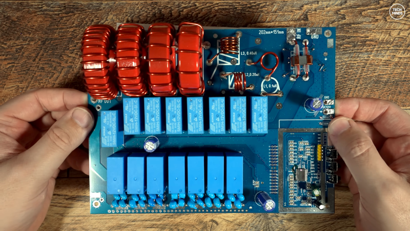
Something that all radio amateurs encounter sooner or later is the subject of impedance matching. If you’d like to make sure all that power is transferred from your transmitter into the antenna and not reflected back into your power amplifier, there’s a need for the impedance of the one to match that of the other. Most antennas aren’t quite the desired 50 ohms impedance, so part of the standard equipment becomes an antenna tuner — an impedance matching network. For high-power hams these are big boxes full of chunky variable capacitors and big air cored inductors, but that doesn’t exclude the low-power ham from the impedance matching party. [Barbaros Aşuroğlu WB2CBA] has designed the perfect device for them: the credit card ATU.

The circuit of an antenna tuner is simple enough, two capacitors and an inductor in a so-called Pi-network because of its superficial resemblance to the Greek letter Pi. The idea is to vary the capacitances and inductance to find the best match, and on this tiny model it’s done through a set of miniature rotary switches. There are a set of slide switches to vary the configuration or switch in a load, and there’s even a simple matching indicator circuit.

We like this project, in that it elegantly provides an extremely useful piece of equipment, all integrated into a tiny footprint. It’s certainly not the first ATU we’ve brought you.

Thanks [ftg] for the tip!


Farewell MFJ

We were sad to hear that after 52 years in operation, iconic ham radio supplier MFJ will close next month. On the one hand, it is hard not to hear such news and think that it is another sign that ham radio isn’t in a healthy space. After all, in an ideal world, [Martin Jue] — the well-known founder of MFJ — would have found an anxious buyer. Not only is the MFJ line of ham radio gear well regarded, but [Martin] had bought other ham radio-related companies over the years, such as Ameritron, Hygain, Cushcraft, Mirage, and Vectronics. Now, they will all be gone, too.

However, on a deeper reflection, maybe we shouldn’t see it as another nail in ham radio’s coffin. It is this way in every industry. There was a time when it was hard to imagine ham radio without, say, Heathkit. Yet they left, and the hobby continued. We could name a slew of other iconic companies that had their day: Eico, Hammarlund, Hallicrafters, and more. They live on at hamfests, their product lines are frozen in time, and we’re sure we’ll see a used market for MFJ gear well into the next century.


Maybe you aren’t a ham and wonder why you would care. Turns out MFJ made things of interest to anyone who worked with RF transmitting or receiving. If you were a shortwave listener, they had antennas and related gear for you. They also made antenna analyzers and network analyzers that were very cost-effective compared to other options. If you wanted clean power supplies, MFJ had quite the selection of those. They even had a great selection of variable capacitors and inductors, which are tough to find in small quantities. You could even get air-wound coil stock, knobs, meters, and toroids.

Sure, most of what they sold was things only hams or other radio operators wanted—that was the nature of the company. But their loss will be felt by more than just the ham community. Someone, of course, will step into the void as they always do.

So farewell MFJ. We will miss you, but we look forward to meeting your replacement, whoever that might be. While you can spend a lot of money on ham radio, you can get started for $50 or less. Oddly, we haven’t directly featured much MFJ gear on Hackaday over the years, but we have mentioned a few.


A Practical Guide To Understanding How Radios Work

How may radios do you own? Forget the AM/FM, GMRS/FRS radios you listen to or communicate with. We’re talking about the multiple radios and antennae in your phone, your TV, your car, your garage door opener, every computing device you own- you get the idea. It’s doubtful that you can accurately count them even in your own home. But what principles of the electromagnetic spectrum allow radio to work, and how do antenna design, modulation, and mixing affect it? [Michał Zalewski] aka [lcamtuf] aims to inform you with his excellent article Radios, how do they work?

A simple illustration compares a capacitor to a dipole antenna.

For those of you with a penchant for difficult maths, there’s some good old formulae published in the article that’ll help you understand the physics of radio. For the rest of us, there are a plethora of fantastic illustrations showing some of the less obvious principals, such as why a longer diploe is more directional than a shorter dipole.

The article opens with a thought experiment, explaining how two dipole antennae are like capacitors, but then also explains how they are different, and why a 1/4 wave dipole saves the day. Of course it doesn’t stop there. [lcamtuf]’s animations show the action of a sine wave on a 1/4 wave dipole, bringing a nearly imaginary concept right into the real world, helping us visualize one of the most basic concepts of radio.

Now that you’re got a basic understanding of how radios work, why not Listen to Jupiter with your own homebrew receiver?


How Much Bandwidth Does CW Really Occupy?

Amateur radio license exams typically have a question about the bandwidths taken up by various modulation types. The concept behind the question is pretty obvious — as guardians of the spectrum, operators really should know how much space each emission type occupies. As a result, the budding ham is left knowing that continuous wave (CW) signals take up a mere 150 Hertz of precious bandwidth.

But is that really the case? And what does the bandwidth of a CW signal even mean, anyway? To understand that, we turn to [Alan (W2AEW)] and his in-depth look at CW bandwidth. But first, one needs to see that CW signals are a bit special. To send Morse code, the transmitter is not generating a tone for the dits and dahs and modulating a carrier wave, rather, the “naked” carrier is just being turned on and off by the operator using the transmitter’s keyer. The audio tone you hear results from mixing the carrier wave with the output of a separate oscillator in the receiver to create a beat frequency in the audio range.

That seems to suggest that CW signals occupy zero bandwidth since no information is modulated onto the carrier. But as [Alan] explains, the action of keying the transmitter imposes a low-frequency square wave on the carrier, so the occupied bandwidth of the signal depends on how fast the operator is sending, as well as the RF rise and fall time. His demonstration starts with a signal generator modulating a 14 MHz RF signal with a simple square wave at a 50% duty cycle. By controlling the keying frequency, he mimics different code speeds from 15 to 40 words per minute, and his fancy scope measures the occupied bandwidth at each speed. He’s also able to change the rise and fall time of the square wave, which turns out to have a huge effect on bandwidth; the faster the rise-fall, the larger the bandwidth.

It’s a surprising result given the stock “150 Hertz” answer on the license exam; in fact, none of the scenarios [Allen] tested came close to that canonical figure. It’s another great example of the subtle but important details of radio that [Alan] specializes in explaining.