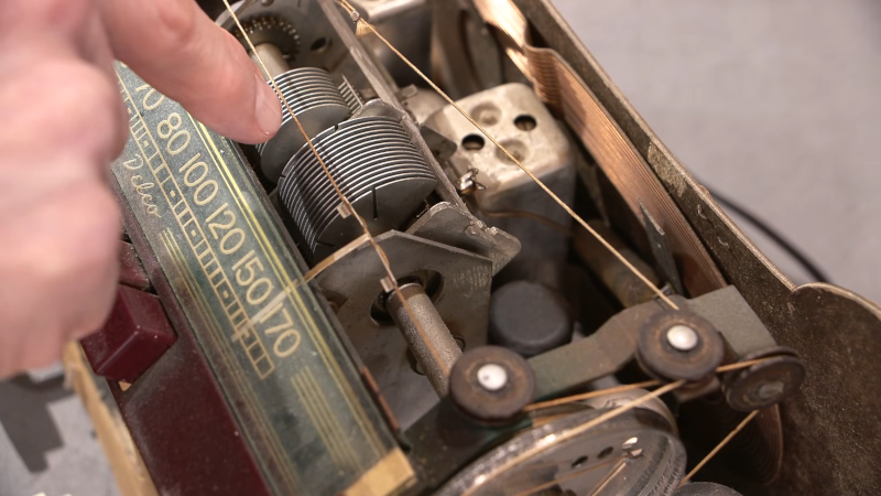
If you’ve seen a big air-variable capacitor, you may have noticed that some of the plates may have slots cut into them. Why? [Mr Carlson] has the answer in the video below. The short answer: you can bend the tabs formed by the slots to increase or decrease the capacitance by tiny amounts for the purpose of tuning.
For example, if you have a radio receiver with a dial, you can adjust the capacitor to make certain spots on the dial have an exact frequency. Obviously, you can only adjust in bands depending on how many slots are in the capacitor. Sometimes the adjustments aren’t setting the oscillator’s frequency. For example, the Delco radio he shows uses the capacitor to peak the tuning at the specified frequency.
You usually only find the slots on the end plates and, as you can see in the video, not all capacitors have the slots. Of course, bending the plates with or without slots will make things change. Just don’t bend enough to short to an adjacent plate or the fixed plates when the capacitor meshes.
Unless you are over a certain age, you probably take it for granted that electronic gadgets you buy have some FCC marking on them. But it wasn’t always true. [Ernie] submits that the FCC’s regulation of the computer industry was indirectly the result of the success of CB radio in that same time period.
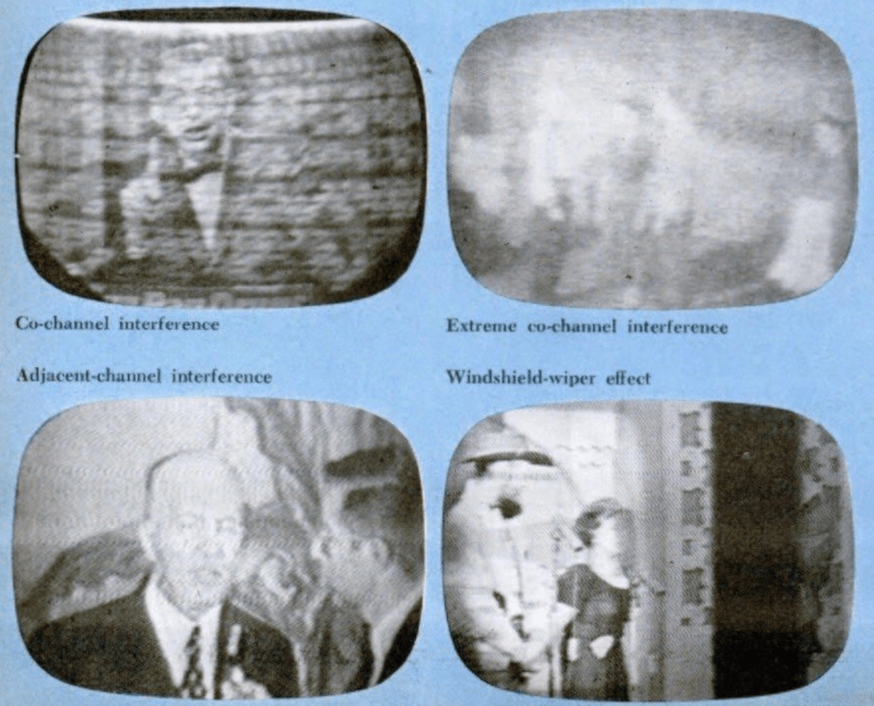
Today, there is a high chance you don’t watch TV directly over the airwaves or even consume audio from a traditional radio station. Even if you do, the signal is increasingly likely to be digital. But only analog radio and TV were highly susceptible to interference. When a professional radio station or the power company interfered with you watching I Love Lucy, you could count on them to resolve it. Even ham radio operators, a small segment of the population, would, in general, graciously help you if their transmissions interfered with your equipment.
Never mind that, in many cases, it was the cheap TV or some other problem on the receiving end. Then there was another source of potential interference: CB radio. At first, you were about as likely to encounter a CB operator as a ham radio operator. But then in the 1970s, CB exploded, becoming a cultural phenomenon, and you can hear what a state it was in by watching the contemporary TV report in the video below.
This explosion of operators who did nothing more than apply for a license (if they even bothered to do so) and bought their equipment at a local store had no idea how to help curb interference, even if they wanted to. In 1977, the AP reported that 83% of the FCC’s TV interference complaints involved CB radio.
Early computers were also very noisy on the radio bands. So much so that early attempts at computer audio output were simply modulating the radio frequency interference. Again, at first, this wasn’t a huge problem. But as computers became more common, so did computer-related interference, and the FCC didn’t want to deal with another CB radio-style explosion.
The rest is, as they say, history, and [Ernie] covers it all in the post. Getting a product approved by the FCC isn’t trivial, but if you have to do it, we have some advice.
De Icom IC-905 is het broertje van de IC-705 en gemaakt voor het SHF bereik (1,2 GHZ tot 10 GHz) en over de ontwikkeling ervan schreef Icom een interessant en 42 pagina’s tellend artikel. Dit kun je HIER downloaden.
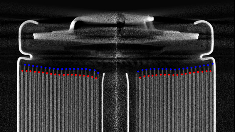
Lithium-ion cells deliver very high energy densities compared to many other battery technologies, but they bring with them a danger of fire or explosion if they are misused. We’re mostly aware of the battery conditioning requirements to ensure cells stay in a safe condition, but how much do we know about the construction of the cells as a factor? [Lumafield] is an industrial imaging company, and to demonstrate their expertise, they’ve subjected a large number of 18650 cells from different brands to a CT scan.
The construction of an 18650 sees the various layers of the cell rolled up in a spiral inside the metal tube that makes up the cell body. The construction of this “jellyroll” is key to the quality of the cell. [Lumafield’s] conclusions go into detail over the various inconsistencies in this spiral, which can result in cell failure. It’s important that the edges of the spiral be straight and that there is no electrode overhang. Perhaps unsurprisingly, they find that cheap no-name cells are poorly constructed and more likely to fail, but it’s also interesting to note that these low-quality cells also have fewer layers in their spiral.
We hope that none of you see more of the inside of a cell in real life than you have to, as they’re best left alone, but this report certainly sheds some light as to what’s going on inside a cell. Of course, even the best cells can still be dangerous without protection.
I often ask people: What’s the most important thing you need to have a successful fishing trip? I get a lot of different answers about bait, equipment, and boats. Some people tell me beer. But the best answer, in my opinion, is fish. Without fish, you are sure to come home empty-handed.
On a recent visit to Bletchley Park, I thought about this and how it relates to World War II codebreaking. All the computers and smart people in the world won’t help you decode messages if you don’t already have the messages. So while Alan Turing and the codebreakers at Bletchley are well-known, at least in our circles, fewer people know about Arkley View.
The problem was apparent to the British. The Axis powers were sending lots of radio traffic. It would take a literal army of radio operators to record it all. Colonel Adrian Simpson sent a report to the director of MI5 in 1938 explaining that the three listening stations were not enough. The proposal was to build a network of volunteers to handle radio traffic interception.
That was the start of the Radio Security Service (RSS), which started operating out of some unused cells at a prison in London. The volunteers? Experienced ham radio operators who used their own equipment, at first, with the particular goal of intercepting transmissions from enemy agents on home soil.
At the start of the war, ham operators had their transmitters impounded. However, they still had their receivers and, of course, could all read Morse code. Further, they were probably accustomed to pulling out Morse code messages under challenging radio conditions.
Over time, this volunteer army of hams would swell to about 1,500 members. The RSS also supplied some radio gear to help in the task. MI5 checked each potential member, and the local police would visit to ensure the applicant was trustworthy. Keep in mind that radio intercepts were also done by servicemen and women (especially women) although many of them were engaged in reporting on voice communication or military communications.
Early Days
The VIs (voluntary interceptors) were asked to record any station they couldn’t identify and submit a log that included the messages to the RSS.
The hams of the RSS noticed that there were German signals that used standard ham radio codes (like Q signals and the prosign 73). However, these transmissions also used five-letter code groups, a practice forbidden to hams.
Thanks to a double agent, the RSS was able to decode the messages that were between agents in Europe and their Abwehr handlers back in Germany (the Abwehr was the German Secret Service) as well as Abwehr offices in foreign cities. Later messages contained Enigma-coded groups, as well.
Between the RSS team’s growth and the fear of bombing, the prison was traded for Arkley View, a large house near Barnet, north of London. Encoded messages went to Bletchley and, from there, to others up to Churchill. Soon, the RSS had orders to concentrate on the Abwehr and their SS rivals, the Sicherheitsdienst.
Change in Management
In 1941, MI6 decided that since the RSS was dealing with foreign radio traffic, they should be in charge, and thus RSS became SCU3 (Special Communications Unit 3).
There was fear that some operators might be taken away for normal military service, so some operators were inducted into the Army — sort of. They were put in uniform as part of the Royal Corps of Signals, but not required to do very much you’d expect from an Army recruit.
Those who worked at Arkley View would process logs from VIs and other radio operators to classify them and correlate them in cases where there were multiple logs. One operator might miss a few characters that could be found in a different log, for example.
It soon became clear that the RSS needed full-time monitoring, so they built a number of Y stations with two National HRO receivers from America at each listening position. There were also direction-finding stations built in various locations to attempt to identify where a remote transmitter was.
Many of the direction finding operators came from VIs. The stations typically had four antennas in a directional array. When one of the central stations (the Y stations) picked up a signal, they would call direction finding stations using dedicated phone lines and send them the signal.
The operator would hear the phone signal in one ear and the radio signal in the other. Then, they would change the antenna pattern electrically until the signal went quiet, indicating the antenna was electrically pointing away from the signals.
The DF operator would hear this signal in one earpiece. They would then tune their radio receiver to the right frequency and match the signal from the main station in one ear to the signal from their receiver in the other ear. This made sure they were measuring the correct signal among the various other noise and interference. The DF operator would then take a bearing by rotating the dial on their radiogoniometer until the signal faded out. That indicated the antenna was pointing the wrong way which means you could deduce which way it should be pointing.
The central station could plot lines from three direction finding stations and tell the source of a transmission. Sort of. It wasn’t incredibly accurate, but it did help differentiate signals from different transmitters. Later, other types of direction-finding gear saw service, but the idea was still the same.
Interesting VIs
Most of the VIs, like most hams at the time, were men. But there were a few women, including Helena Crawley. She was encouraged to marry her husband Leslie, another VI, so they could be relocated to Orkney to copy radio traffic from Norway.
In 1941, a single VI was able to record an important message of 4,429 characters. He was bedridden from a landmine injury during the Great War. He operated from bed using mirrors and special control extensions. For his work, he receive the British Empire Medal and a personal letter of gratitude from Churchill.
Results
Because of the intercepts of the German spy agency’s communications, many potential German agents were known before they arrived in the UK. Of about 120 agents arriving, almost 30 were turned into double agents. Others were arrested and, possibly, executed.
By the end of the war, the RSS had decoded around a quarter of a million intercepts. It was very smart of MI5 to realize that it could leverage a large number of trained radio operators both to cover the country with receivers and to free up military stations for other uses.
You turn the dial on your radio, and hear a powerful source of interference crackle in over the baseline noise. You’re interested as to where it might be coming from. You’re receiving it well, and the signal strength is strong, but is that because it’s close or just particularly powerful? What could it be? How would you even go about tracking it down?
When it comes to hunting down radio transmissions, Justin McAllister and Nick Foster have a great deal of experience in this regard. They came down to the 2024 Hackaday Superconference to show us how it’s done.
Transmissions From Where?
Nick Foster opens the talk by discussing how the first job is often to figure out what you’re seeing when you pick up a radio transmission. “The moral of this talk is that your hardware is always lying to you,” says Nick. “In this talk, we’re going to show you how your radio lies to you, what you can do about it, and if your hardware is not lying to you, what is that real station that you’re looking at?” It can be difficult to tease out the truth of what the radio might seem to be picking up. “How do we determine what a signal actually is?” he asks. “Is it a real signal that we’re looking at which is being transmitted deliberately from somebody else, or is it interference from a bad power supply, or is it a birdie—a signal that’s created entirely within my own radio that doesn’t exist at all?”
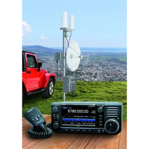
There are common tools used to perform this work of identifying just what the radio is actually picking up and where it’s coming from. Justin goes over some of the typical hardware, noting that the RX-888 is a popular choice for software-defined radio that can be tuned across HF, VHF, and UHF bands. It’s highly flexible, and it’s affordable to boot, as is the Web-888 which can be accessed conveniently over a web browser. Other common SDRs are useful, too, as are a variety of filters that can aid with more precise investigations.
Justin demonstrates an errant radio emission from the brushed motor in his furnace, noting how it varies in bandwidth—a surefire tell versus intentional radio transmissions.
Establishing a grounding in reality is key, Justin steps up to explain. “We turn our SDR on, we stick [on] the little antenna that comes with it, and we start looking at something,” says Justin. “Are the signals that we see there actually real?” He notes that there are some basics to consider right off the bat. “One key point to make is that nobody makes money or has good communication using an unmodulated carrier,” he points out. “If you just see a tone somewhere, it might be real, but there’s a good chance that it’s not.”
It’s perhaps more likely unintentional radiation, noise, or something generated inside the hardware itself on your end. It’s also worth looking at whether you’re looking at a fixed frequency or a changing frequency to pin things down further. Gesturing to a spectrogram, he notes that the long, persistent lines on the spectrogram are usually clues to more intentional transmissions. Intermittent squiggles are more often unintentional. Justin points at some that he puts down to the emissions from arc welders, sparking away as they do, and gives an example of what emissions from typical switching power supplies look like.
There are other hints to look out for, too. Real human-made signals tend to have some logic to them. Justin notes that real signals usually make “efficient” use of spectrum without big gaps or pointless repetition. It’s also possible to make judgement calls as to whether a given signal makes sense for the band it appears to be transmitted in. Schedule can be a tell, too—if a signal always pops up when your neighbor gets home at 6 PM, it might just be coming from their garage door remote. Justin notes a useful technique for hunting down possible nearby emitters—”Flipping on and off switches is a real good way of figuring out—is it close to me or not?”
SDRs are hugely flexible, but they also have very open front-ends that can lead to some confusing output.
Nick follows up by discussing the tendency of sampling radios to show up unique bizarre transmissions that aren’t apparent on an analog receiver. “One of the curses of the RTL-SDR is actually one of its strengths… it has a completely wide open front end,” notes Nick. “Its ADC which is sampling and capturing the RF has basically nothing except an amplifier in between it and whatever crud you’re putting into it.” This provides great sensitivity and frequency agility, but there’s a catch—”It will happily eat up and spit out lots of horrible stuff,” says Nick. He goes on to explain various ways such an SDR might lie to the user. A single signal might start popping up all over the frequency band, or interfere with other signals coming in from the antenna. He also highlights a great sanity check for hunting down birdies—”If it’s always there, if it’s unchanging, if you unplug your antenna and you still hear it—it’s probably generated in your radio!”
The rest of the talk covers locating transmissions—are they in your house, in the local community, or from even farther afield? It explores the technique of multilateration, where synchronized receivers and maths are used to measure the time differences seen in the signal at each point to determine exactly where a transmission is coming from. The talk also goes over common sources of noise in residential settings—cheap PWM LED lights, or knock-off laptop chargers being a prime example in Nick’s experience. There’s also a discussion of how the noise floor has shifted up a long way compared to 50 years ago, now that the world is full of so many more noise-emitting appliances.
Ultimately, the duo of Justin and Nick brought us a great pun-filled talk on sleuthing for the true source of radio transmissions. If you’ve ever wondered about how to track down some mystery transmitter, you would do well to watch and learn from the techniques explored within
Op donderdag 29 mei liet Velddaggroep Zuid-Limburg een weerballon op vanuit Dochamps (B). Mark PC9DB en Thijs PE1RLN lieten al eerder ballonnen op om te volgen, tijdens deze velddag krijgt de rest ook eens te zien hoe je dit fenomeen aanpakt. Gewapend met een fles helium en een precieze weegschaal wordt de ballon gevuld en voorzien van z’n payload. Deze bestaat uit een gebruikte weersonde met speciale lithium batterijen die opnieuw is geprogrammeerd om in de 70cm band met het Horus protocol z’n telemetrie uit te zenden.
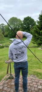
Het miezert een beetje, niet ideaal maar we gokken het erop. De ballon wordt opgelaten en gelukkig maakt hij snel hoogte en begint z’n reis over de wereld.
Aanvankelijk vertrok de ballon weliswaar voortvarend maar door de regen werd de ballon te zwaar en begon deze te dalen… Er wordt overlegd of we de ballon gaan zoeken of het erbij laten.
Mark, Thijs en Tony gingen met de auto er achteraan, richting de laatst ontvangen positie. Maar ja, dat is niet per se de locatie waar de ballon uiteindelijk is geland dus dan is goede raad duur… Met portofoon en laptop in de hand dan maar door het bos het veld in, in de hoop op een signaal:
Het was gelukkig goed weer waardoor onze avonturiers boven op de heuvel konden komen alwaar ze het signaal opnieuw oppikten! De ballon moest dus in de buurt zijn dus werd de portofoon weer op de laptop aangesloten en werd gewacht op de volgende positie.
Gotcha!
Maar ja, dat was natuurlijk niet op de gewenste plek dus de woudlopers moesten door een aantal velden door anderhalve meter hoog gras om zodoende in de buurt te komen van de ballon.
Maar goed, het was niet te warm en een gezonde wandeling kon geen kwaad.
Door metershoog gras, pas ingezaaid gewas, door kuddes koeien richting het bosje waar de ballon zou moeten zijn. Hoge bomen… Oei. Op Google Maps leek het nog een laag bosje maar dit zijn stevige bomen en als de ballon boven in de boom hangt, zijn we de sjaak.
Maar niet gewanhoopt, het team komt dichterbij en eindelijk zijn we op dezelfde positie aangekomen waar de ballon telkens z’n positie van opgeeft. Maar ja, ga maar zoeken. Turend in de lucht naar de transparante ballon vindt Mark uiteindelijk ons verloren experiment:
In een klein boompje, je kunt er zo bij! Dat is nog eens geluk hebben. Na de ballon uit de boom gevist te hebben zonder lekkage wordt gecontroleerd of deze nog wel wil stijgen: dan moeten we ‘m eerst afdrogen natuurlijk want hij was niet voor niets omlaag gekomen. De ballon is kletsnat van de regendruppels en met een netto lift van ~10 gram zijn een paar druppels al gauw net iets teveel.
We zoeken het hogerop om de ballon opnieuw het luchtruim te laten opzoeken. Het waait flink maar dat mag de pret niet drukken.
Zo. En nu weer dat hele takke eind terug wandelen in de hoop dat de ballon deze keer een langere reis zal maken. Terug aangekomen op de velddag blijkt dat de ballon buiten het bereik is geraakt van de eigen ontvanger, dat kan van alles betekenen… De hele avond lijkt het erop dat de ballon wederom ergens is terecht gekomen…
’s Ochtends blijkt echter dat de ballon wel degelijk z’n reis heeft vervolgd! Hij zweeft richting Oostenrijk en we blijven onze vriend volgen via diverse ontvangers:
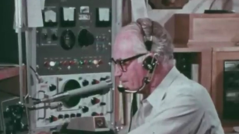
We hear a lot about how ham radio isn’t what it used to be. But what was it like? Well, the ARRL’s film “The Ham’s Wide World” shows a snapshot of the radio hobby in the 1960s, which you can watch below. The narrator is no other than the famous ham [Arthur Godfrey] and also features fellow ham and U.S. Senator [Barry Goldwater]. But the real stars of the show are all the vintage gear: Heathkit, Swan, and a very oddly placed Drake.
The story starts with a QSO between a Mexican grocer and a U.S. teenager. But it quickly turns to a Field Day event. Since the film is from the ARRL, the terminology and explanations make sense. You’ll hear real Morse code and accurate ham lingo.
Is ham radio really different today? Truthfully, not so much. Hams still talk to people worldwide and set up mobile and portable stations. Sure, hams use different modes in addition to voice. There are many options that weren’t available to the hams of the 1960s, but many people still work with old gear and older modes and enjoy newer things like microwave communications, satellite work, and even merging radio with the Internet.
In a case of history repeating itself, there is an example of hams providing communications during a California wildfire. Hams still provide emergency communication in quite a few situations. It is hard to remember that before the advent of cell phones, a significant thing hams like [Barry Goldwater] did was to connect servicemen and scientists overseas to their families via a “phone patch.” Not much of that is happening today, of course, but you can still listen in to ham radio contacts that are partially over the Internet right in your web browser.
Een Duitse hacker heeft een satelliet tot leven weten te wekken die sinds 2013 niet meer werkte. Daarvoor hoefde PistonMiner niet naar de ruimte; de satelliet kon vanaf de grond weer worden gerepareerd door eerst de telemetrie te herstellen en daarna de originele code te hacken.
Hacker PistonMiner presenteerde de hack tijdens de CCC-hackersconferentie in Hamburg. Het gaat om de satelliet BeeSAT-1, wat staat voor de Berlin Experimental and Education Satellite. Dat is een kleine cubesat van 10x10x10cm die in 2009 door de Technische Universiteit van Berlijn werd gelanceerd. In 2011 begon de satelliet foutieve telemetrie terug te sturen naar de aarde. Nadat de beheerders de satelliet daarop overzetten naar de back-upcomputer, kreeg ook die in 2013 problemen. Sindsdien is de satelliet, die op een hoogte van 700 kilometer boven de aarde vliegt, niet meer bruikbaar. BeeSAT-1 stuurt namelijk alleen nog nullen door als telemetrie.
PistonMiner ontdekte al snel dat het niet mogelijk was om zomaar een firmware-update naar de satelliet te sturen. De functionaliteit daarvoor werd namelijk niet afgemaakt voor de lancering. Maar de hacker ontdekte ook dat de computer niet fysiek stuk was gegaan door bijvoorbeeld straling in de ruimte; in diens talk heeft PistonMiner het over softwareproblemen. De cubesat stuurt bijvoorbeeld data terug die corrupt lijkt te zijn. Dat kan in theorie gerepareerd worden in het flashgeheugen. PistonMiner ontdekte dat het probleem lag in de bootcounter van de computer aan boord. De hacker bouwde daarom een eigen BeeSAT hier op aarde om te simuleren of het probleem op afstand kon worden gerepareerd.
Daar kwam uit dat het mogelijk moest zijn om de vtables van de satellietsoftware, die in C++ werd geschreven, te onderscheppen. Zo kon PistonMiner commando’s uitvoeren op de satelliet zelf. In de talk vertelt de hacker ook hoe het mogelijk werd om de camera van de satelliet uiteindelijk te beheren. Die werkte aanvankelijk niet omdat er voorafgaand aan de lancering te weinig tijd was de firmware daarvoor te schrijven, maar PistonMiner kreeg het alsnog voor elkaar die bug te repareren en de camera werkend te krijgen.
PistonMiner vertelt in de talk verder ook hoe ingewikkeld het was om in de eerste plaats contact te leggen met de satelliet; die vliegt eens per anderhalf uur over Berlijn, waarin de hacker maximaal een kwartiertje de tijd had commando’s door te voeren naar de kleine cubesat. Uiteindelijk is dat wel gelukt. BeeSAT-1 is weer operationeel en kan worden gebruikt voor zijn originele doel om bijvoorbeeld signalen naar radioamateurs te sturen.
Update, 16.55uur – aangepast dat CCC in Hamburg plaatsvond en niet in Berlijn.
We were sad to hear that after 52 years in operation, iconic ham radio supplier MFJ will close next month. On the one hand, it is hard not to hear such news and think that it is another sign that ham radio isn’t in a healthy space. After all, in an ideal world, [Martin Jue] — the well-known founder of MFJ — would have found an anxious buyer. Not only is the MFJ line of ham radio gear well regarded, but [Martin] had bought other ham radio-related companies over the years, such as Ameritron, Hygain, Cushcraft, Mirage, and Vectronics. Now, they will all be gone, too.
However, on a deeper reflection, maybe we shouldn’t see it as another nail in ham radio’s coffin. It is this way in every industry. There was a time when it was hard to imagine ham radio without, say, Heathkit. Yet they left, and the hobby continued. We could name a slew of other iconic companies that had their day: Eico, Hammarlund, Hallicrafters, and more. They live on at hamfests, their product lines are frozen in time, and we’re sure we’ll see a used market for MFJ gear well into the next century.
Maybe you aren’t a ham and wonder why you would care. Turns out MFJ made things of interest to anyone who worked with RF transmitting or receiving. If you were a shortwave listener, they had antennas and related gear for you. They also made antenna analyzers and network analyzers that were very cost-effective compared to other options. If you wanted clean power supplies, MFJ had quite the selection of those. They even had a great selection of variable capacitors and inductors, which are tough to find in small quantities. You could even get air-wound coil stock, knobs, meters, and toroids.
Sure, most of what they sold was things only hams or other radio operators wanted—that was the nature of the company. But their loss will be felt by more than just the ham community. Someone, of course, will step into the void as they always do.
So farewell MFJ. We will miss you, but we look forward to meeting your replacement, whoever that might be. While you can spend a lot of money on ham radio, you can get started for $50 or less. Oddly, we haven’t directly featured much MFJ gear on Hackaday over the years, but we have mentioned a few.


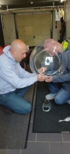
 Op donderdag 29 mei liet Velddaggroep Zuid-Limburg een weerballon op vanuit Dochamps (B). Mark PC9DB en Thijs PE1RLN lieten al eerder ballonnen op om te volgen, tijdens deze velddag krijgt de rest ook eens te zien hoe je dit fenomeen aanpakt. Gewapend met een fles helium en een precieze weegschaal wordt de ballon gevuld en voorzien van z’n payload. Deze bestaat uit een gebruikte weersonde met speciale lithium batterijen die opnieuw is geprogrammeerd om in de 70cm band met het Horus protocol z’n telemetrie uit te zenden.
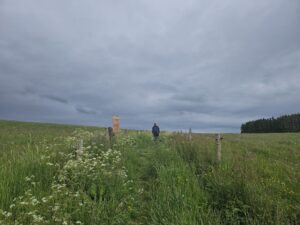 Het was gelukkig goed weer waardoor onze avonturiers boven op de heuvel konden komen alwaar ze het signaal opnieuw oppikten! De ballon moest dus in de buurt zijn dus werd de portofoon weer op de laptop aangesloten en werd gewacht op de volgende positie.
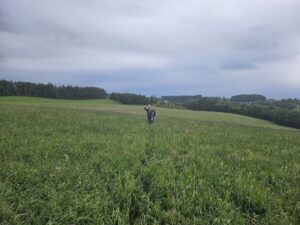 Maar goed, het was niet te warm en een gezonde wandeling kon geen kwaad.
 In een klein boompje, je kunt er zo bij! Dat is nog eens geluk hebben. Na de ballon uit de boom gevist te hebben zonder lekkage wordt gecontroleerd of deze nog wel wil stijgen: dan moeten we ‘m eerst afdrogen natuurlijk want hij was niet voor niets omlaag gekomen. De ballon is kletsnat van de regendruppels en met een netto lift van ~10 gram zijn een paar druppels al gauw net iets teveel.
 Zo. En nu weer dat hele takke eind terug wandelen in de hoop dat de ballon deze keer een langere reis zal maken. Terug aangekomen op de velddag blijkt dat de ballon buiten het bereik is geraakt van de eigen ontvanger, dat kan van alles betekenen… De hele avond lijkt het erop dat de ballon wederom ergens is terecht gekomen…
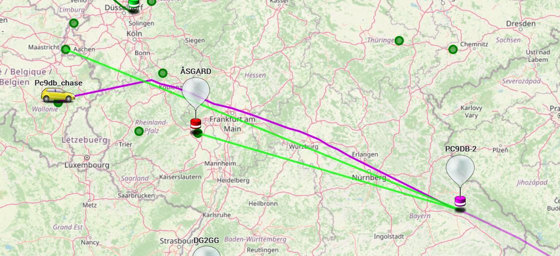
 Een Duitse hacker heeft een satelliet tot leven weten te wekken die sinds 2013 niet meer werkte. Daarvoor hoefde PistonMiner niet naar de ruimte; de satelliet kon vanaf de grond weer worden gerepareerd door eerst de telemetrie te herstellen en daarna de originele code te hacken.
/i/2007162470.png?f=imagenormal)