Vind je het leuk en interessant om op zondag naar de ronde te luisteren? Misschien vind je het ook wel leuk om ‘m zelf eens te leiden? Dat kan!
We zoeken nog mensen om de ronde te leiden. Er wordt ruim van tevoren een planning gemaakt en je kunt de ronde je eigen invulling geven. Uiteraard zijn er wat standaard rubrieken zoals activiteiten en markten maar jouw eigen interesses bepalen nu juist het karakter en het succes van elke uitzending.
Beginnen met de ronde leiden kan met hulp van een aantal ervaren rondeleiders die je helpen met het voorbereiden zodat je zelf ervaring krijgt en van de “plankenkoorts” afkomt. Je wordt dus niet in het diepe gegooid maar kunt rekenen op support!
Heb je interesse? Stuur een mailtje naar pe1rln@vrza.nl en we nemen contact met je op.
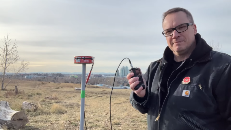
If you’d have asked us for odds on whether you could successfully turn a canned ham into an amateur radio antenna, we’d have declined the offer. Now, having seen [Ben Eadie (VE6SFX)]’s “hamtenna” project, we’d look at just about any “Will it antenna?” project with a lot less skepticism than before.
To be painfully and somewhat unnecessarily clear about [Ben]’s antenna, the meat-like product itself is not in the BOM for this build, although he did use it as sustenance. Rather, it was the emptied and cleaned metal can that was the chief component of the build, along with a few 3D printed standoffs and the usual feedline and connectors. This is a slot antenna, a design [Ben] recently experimented with by applying copper foil tape to his car’s sunroof. This time around, the slot was formed by separating the top and bottom of the can using the standoffs and electrically connecting them with a strip of copper tape.
Connected to a stub of coax and a BNC connector, a quick scan with a NanoVNA showed a fantastic 1.26:1 SWR in the center of the 70-cm ham band, and a nearly flat response all the way across the band. Results may vary depending on the size of canned ham you sacrifice for this project; [Ben]’s can measured just about 35 cm around, a happy half-wavelength coincidence. And it actually worked in field tests — he was able to hit a local repeater and got good signal reports. All that and a sandwich? Not too shabby.
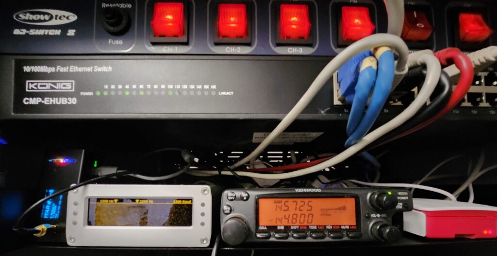
Misschien heb je de laatste tijd wat piepjes en ruis over de repeater gehoord, dat komt omdat er wordt gewerkt aan een upgrade aan de ontvangstzijde. Niet ver van de repeater wordt een extra ontvanger via internet verbonden zodat de gevoeligheid wordt verbeterd.
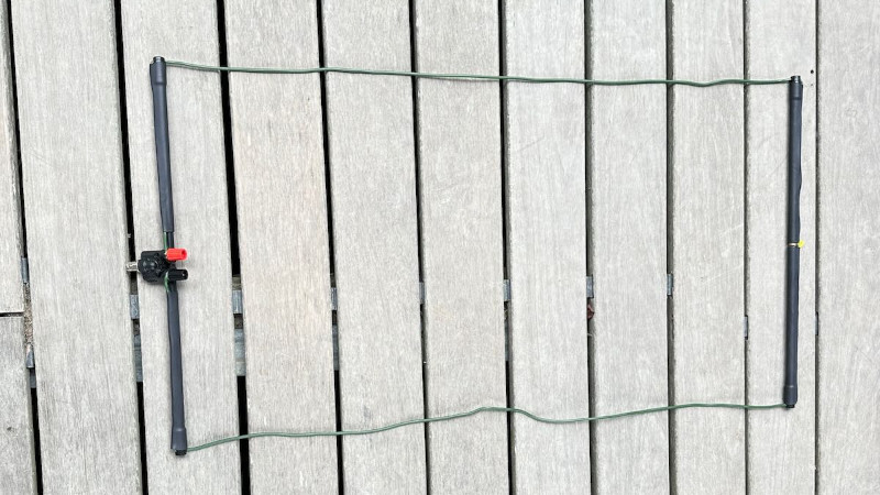
One of amateur radio’s many interests comes in portable operation, taking your radio to an out of the way place, usually a summit, and working the world using only what can be carried in. Often this means using the HF or shortwave bands, but the higher frequencies get a look-in as well. A smaller antenna is no less the challenge when it comes to designing one that can be carried though, and [Thomas Witherspoon] demonstrates this with a foldable loop antenna for the 2 metre band.
The antenna provides a reminder that the higher bands are nothing to be scared of in construction terms, it uses a BNC-to-4 mm socket adapter as its feedpoint, and makes the rectangular shape of the loop with pieces of fiberglass tube. The wire itself is flexible antenna wire, though we’re guessing almost any conductor could be used. The result is a basic but useful antenna that certainly packs down to a very small size, and we can see it would be a useful addition to any portable operator’s arsenal.
Beste leden, vanaf 20 november komt de VRZA bijeen op maandag. In verband met de stookkosten van de grote zaal en de overige activiteiten in het café, bleek de vrijdagavond niet meer geschikt om bijeen te komen. Uit de onlangs gehouden enquête blijkt dat de maandag de grootste voorkeur heeft van de leden, vandaar dat we naar die dag verhuizen.
In verband met vakantie van ’t Volkshuis, vindt er geen bijeenkomst plaats op vrijdag 10 november, ook niet op maandag 13 november. Op maandag 20 november dus de eerstvolgende bijeenkomst!
Heb je je ook aangemeld voor onze Whatsapp groep? Dan ontvang je direct mededelingen van het bestuur zoals wijzigingen in de planning en reminders voor activiteiten zoals beurzen en lezingen. Nog niet aangemeld? Stuur een e-mail naar pe1rln@vrza.nl met je telefoonnummer en je komt in de groep erbij. In deze groep kunnen leden niks plaatsen en ontvangen ze ook geen flauwekul, alleen nuttige informatie.
Door recentelijk 2 dagen waarop het verenigingslokaal gesloten was, bleek dat er behoefte was aan een beter communicatiekanaal.
Wil je op de hoogte zijn van actuele zaken rondom de VRZA Zuid-Limburg? Op tijd een reminder voor een activiteit? Meld je dan nu aan om deel te nemen aan de whatsapp-groep! In deze groep voor leden van de VRZA komt geen flauwekul omdat het een read-only groep is waarop alleen het bestuur een bericht kan plaatsen.
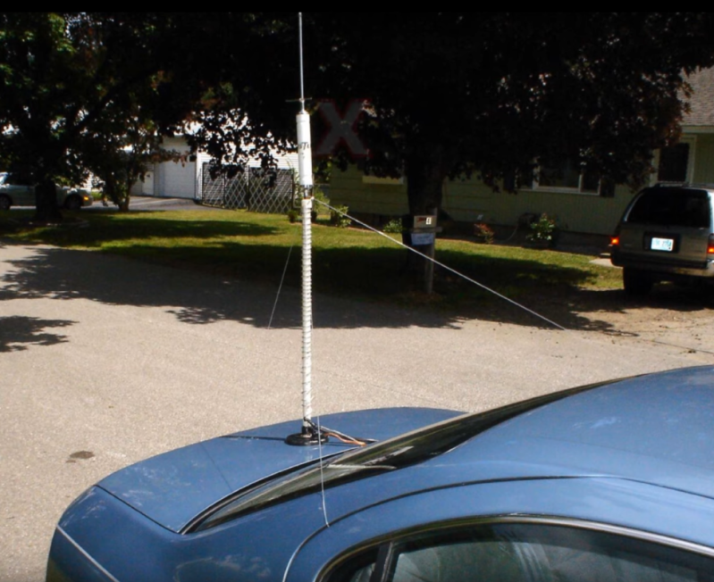
The real action in the world of ham radio is generally in the high frequency bands. Despite the name, these are relatively low-frequency bands by modern standards and the antenna sizes can get a little extreme. After all, not everyone can put up an 80-meter dipole, but ham radio operators have come up with a number of interesting ways of getting on the air anyway. The only problem is that a lot of these antennas don’t seem as though they should work half as well as they do, and [MIKROWAVE1] takes a look back on some of the more exotic radiators.
He does note that for a new ham radio operator it’s best to keep it simple, beginning work with a dipole, but there are still a number of options to keep the size down. A few examples are given using helically-wound vertical antennas or antennas with tuned sections of coaxial cable. From there the more esoteric antennas are explored, such as underground antennas, complex loops and other ways of making a long wire fit in a small space, and even simpler designs like throwing a weight with a piece of wire attached out the window of an apartment building.
While antenna theory is certainly a good start for building antennas, a lot of the design of antennas strays into artistry and even folklore as various hams will have successes with certain types and others won’t. It’s not a one-size-fits-all situation so the important thing is to keep experimenting and try anything that comes to mind as long as it helps get on the air. A good starting point is [Dan Maloney]’s $50 Ham Guide series, and one piece specifically dealing with HF antennas.
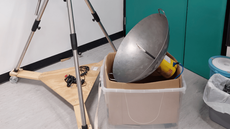
The round bottom of a proper wok is the key to a decent stir fry, but it also makes it hard to use on traditional Western stoves. That’s why many woks end up in a dark kitchen cabinet, unused and unloved. But wait; it turns out that the round bottom of a wok is the perfect shape for gathering something else — radio waves, specifically the 21-cm neutral hydrogen emissions coming from the heart of our galaxy.
Turning a wok into an entry-level radio telescope doesn’t appear to be all that hard, at least judging by what [Leo W.H. Fung] et al detail in their paper (PDF) on “WTH” or “Wok the Hydrogen.” Aside from the wok, which serves as the main reflector, you’ll need a bit of coaxial cable and some stiff copper wire to fashion a small dipole antenna and balun, plus some plastic tubing to support it at the focal point of the reflector. Measuring the wok’s shape and size, which in turn determines its focal point, is probably the hardest part of the build; luckily, the paper includes tips on doing just that. The authors address the controversy of parabolic versus spherical reflectors and arrive at the conclusion that for a radio telescope fashioned from a wok, it just doesn’t matter.
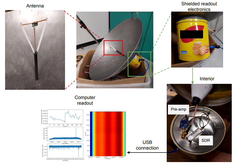
As for the signal processing chain, WTH holds few surprises. A Nooelec Sawbird+ H1 acts as preamp and filter for the 1420-MHz hydrogen line signal, which feeds into an RTL-SDR dongle. Careful attention is paid to proper grounding and shielding to keep the noise floor as low as possible. Mounting the antenna is a decidedly ad hoc affair, and aiming is as simple as eyeballing various stars near the center of the galactic plane — no need to complicate things.
Performance is pretty good: WTH measured the recession velocity of neutral hydrogen to within 20 km/s, which isn’t bad for something cobbled together from scrap. We’ve seen plenty of DIY hydrogen line observatories before, but WTH probably wins the “get on the air tonight” award.
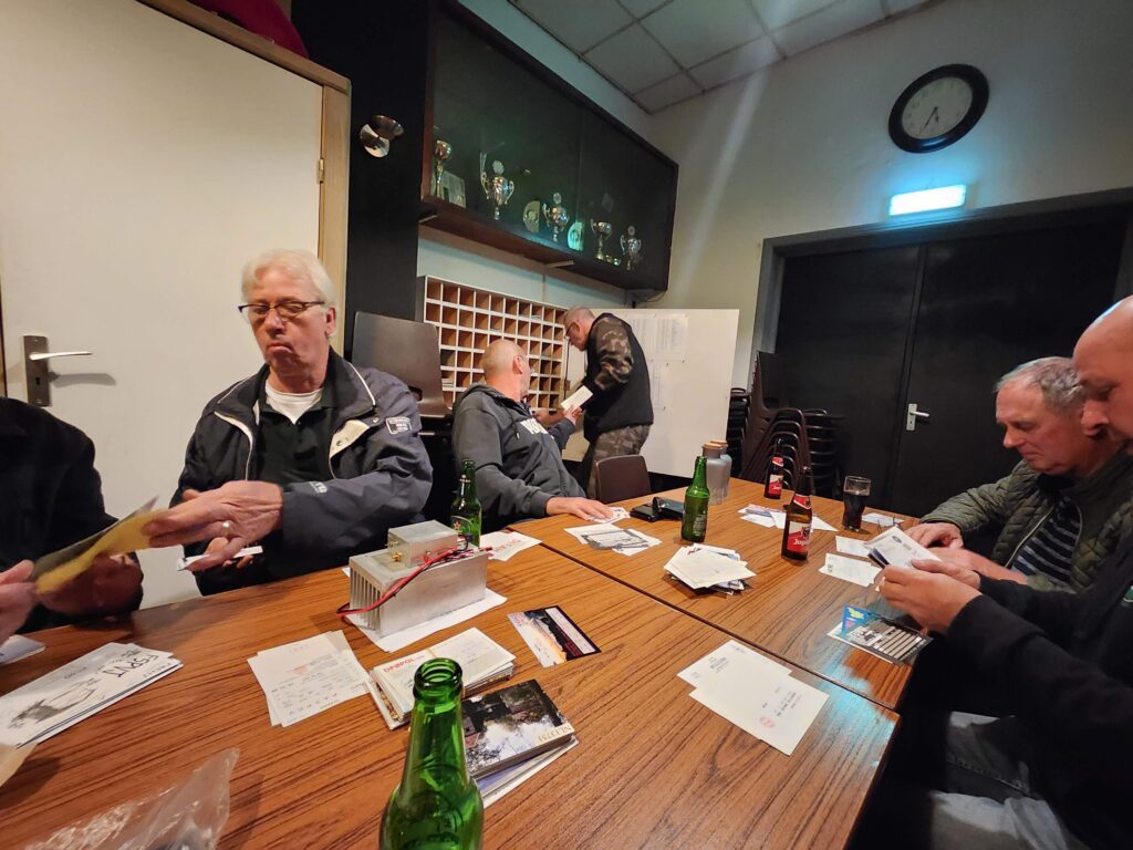
Dankzij Ron PD1RVD hebben we weer een nieuwe regio-QSLmanager en kan de verwerking van alle QSL weer doorgang vinden. Onlangs is de hele clubavond besteed aan het wegwerken van de vertraagde post en liggen alle vakjes weer gevuld erbij.
Kaarten ophalen en afgeven kan elke vrijdagavond. Let er wel op dat je bent aangemeld bij de VRZA voor de ontvangst en je ook een postvakje hebt toegewezen gekregen.
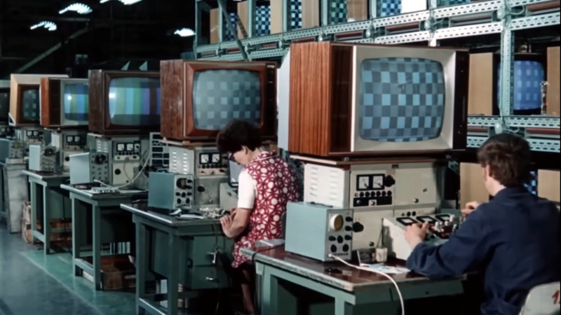
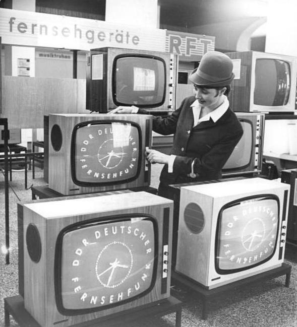
For those of us who lived through the Cold War, there’s still an air of mystery as to what it was like on the Communist side. As Uncle Sam’s F-111s cruised slowly in to land above our heads in our sleepy Oxfordshire village it was at the same time very real and immediate, yet also distant. Other than being told how fortunate we were to be capitalists while those on the communist side lived lives of mindless drudgery under their authoritarian boot heel, we knew nothing of the people on the other side of the Wall, and God knows what they were told about us. It’s thus interesting on more than one level to find a promotional film from the mid 1970s showcasing VEB Fernsehgerätewerk Stassfurt (German, Anglophones will need to enable subtitle translation), the factory which produced televisions for East Germans. It provides a pretty comprehensive look at how a 1970s TV set was made, gives us a gateway into the East German consumer electronics business as a whole, and a chance to see how the East Germany preferred to see itself.
The RFT range of televisions in the Städtisches Kaufhaus exhibition center for the 1968 Leipzig Spring Fair. Bundesarchiv, CC-BY-SA 3.0
The sets in question are not too dissimilar to those you would have found from comparable west European manufacturers in the same period, though maybe a few things such as the use of a tube output stage and the lack of integrated circuits hints at their being a few years behind the latest from the likes of Philips or ITT by 1975. The circuit boards are assembled onto a metal chassis which would have probably been “live” as the set would have derived its power supply by rectifying the mains directly, and we follow the production chain as they are thoroughly checked, aligned, and tested. This plant produces both colour and back-and-white receivers, and since most of what we see appears to be from the black-and-white production we’re guessing that here’s the main difference between East and West’s TV consumers in the mid ’70s.
The film is at pains to talk about the factory as a part of the idealised community of a socialist state, and we’re given a tour of the workers’ facilities to a backdrop of some choice pieces of music. References to the collective and some of the Communist apparatus abound, and finally we’re shown the factory’s Order of Karl Marx. As far as it goes then we Westerners finally get to see the lives of each genosse, but only through an authorised lens.
The TVs made at Stassfurt were sold under the RFT East German technology combine brand, and the factory continued in operation through the period of German re-unification. Given that many former East German businesses collapsed with the fall of the Wall, and that the European consumer electronics industry all but imploded in the period following the 1990s then, it’s something of a surprise to find that it survives today, albeit in a much reduced form. The plant is now owned by the German company TechniSat, and manufactures the latest-spec digital TVs. Meanwhile for those interested in history there’s a museum exhibition in the town (German language, Google Translate link), which looks very much worth a visit should you be motoring across Germany.
As degenerate capitalists we weren’t offered the privilege of buying a TV from the Worker’s Paradise, so we never had the opportunity to see how their quality stacked up to that of the Western models. It’s worth remembering that however rose-tinted our view of the 1970s may be, British-made sets of the period weren’t particularly reliable themselves.
 Vind je het leuk en interessant om op zondag naar de ronde te luisteren? Misschien vind je het ook wel leuk om ‘m zelf eens te leiden? Dat kan!