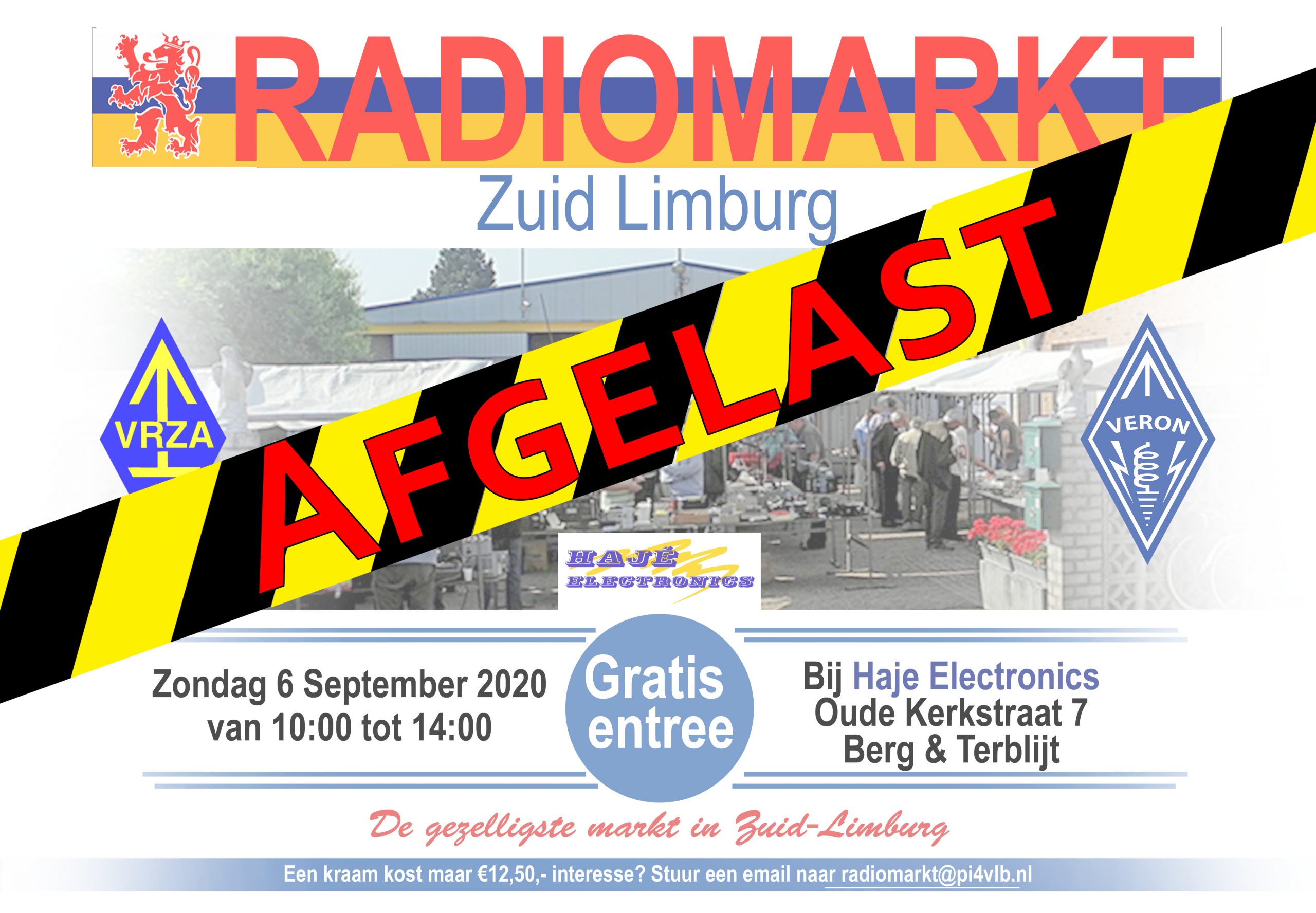
(Inter)Nationale Molendagen 9 en 10 mei 2020 – PA6TIEN
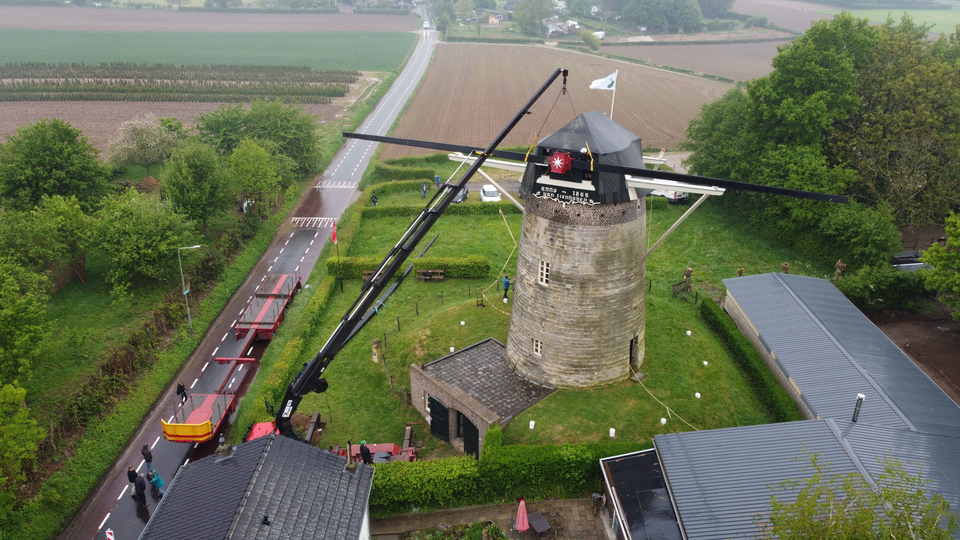
Foto: 1Limburg.nl
(Inter)Nationale Molendagen 9 en 10 mei 2020.
Van Tienhoven Molen Wolfshuis, Bemelen
Radioamateurs Zuid Limburg

Met toestemming van de Stichting Limburgs Landschap.
De Van Tienhovenmolen is, om bekende redenen, niet toegankelijk voor bezoekers!
Er wordt wel gewerkt aan een grondige renovering, waarbij zelfs de wieken voor enkele maanden in restauratie gestuurd worden.
De COVID-19 pandemie regels streng inachtnemend zal deze traditionele velddag, wat uitvoering betreft, een ander dan normaal karakter hebben.
Om binnen de ( steeds veranderende ) corona regels te blijven is nu het volgende voorstel:
Een groep van deelnemende stations in dit event wordt als ( actieve) lijst bekend gemaakt.
Op 9 en 10 mei 2020 kan gebruik worden van de parkeer ruimte en weide rondom de Van Tienhovenmolen, waar men als single operator ( afstand minstens 10 meter van elkaar) uit kan/mag komen als PA6TIEN. Tijdens een verbinding wordt buiten de call PA6TIEN tevens de eigen call en naam vermeld.
Ben je op grote afstand van de Van Tienhovenmolen – home QTH of ergens anders in het Limburgse Heuvelland.. dan kom je uit met de eigen call en als toevoeging /tien.
Verbindingen die gemaakt worden doen mee in een bescheiden contact-estafette.
Er zijn punten ( voor een certificaat of vernoeming op een erelijst) te behalen:
QSO met PA6TIEN 5 punten
QSO met CALL/tien 5 punten
Multiplier voor elke band 2x
Multiplier voor elke mode 2x
Een regiorepeater verbinding op 145.725 MHz. geldt maar één maal ( ja helaas) voor deze puntentelling. Gebruik de repeater voor het afspreken van een sked. De meesten zijn QRV op deze frequentie.
Corona-safe werken staat op NR 1 !!
Tot nu toe deelnemende stations met genoemde banden en modes zijn:
PA6TIEN, PA3DVH, PB7J, PA5RWD, PA8MC, PE1RLN, PD0DX, PA3CBH
Banden: 80m, 40m, 20m, 10m, 2m, 70cm
Modes: FT8, FT4, FM, SSB, CW
Wil je ook meedoen als actief station, in de bovenstaande lijst toegevoegd worden stuur dan een mailtje met vermelding van je call, en de banden + modes waarin je uit wil/kunt komen.
Heb je vragen en ( vooral ) suggesties, dan laat het zeker ook weten
Mail: pa6tien[at]limburgerstraat.nl
PA6TIEN Zuid Limburgse Radio Amateurs
— Nationale Molendagen 9 en 10 mei 2020
De Van Tienhovenmolen Wolfshuis, Bemelen
Gasthuis 79 6268NN Bemelen ( Gemeente Eijsden-Margraten) Limburg Nederland
Geopositie: X: 184257 Y: 316914
N 50.841328 O 5.802546
Maidenhead Loc: JO20vu
Roberto PD0DX , Theo PA3CBH
Hams Cross The Atlantic On UHF
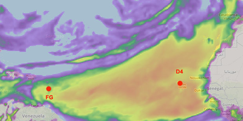
We often think of ham radio operators talking to exotic faraway lands, and that’s true for hams using the HF bands (below 30 MHz), especially if they have nice antennas. Modern living has made it much harder to have those big antenna farms, and today’s ham is more likely talking on VHF or UHF frequencies with very limited range under normal circumstances. Sure, you can use a repeater or bounce your signal from a satellite or the moon, but normal direct communication is normally going to be less than a typical commercial FM radio station. But on April 7th, two hams communicated across the Atlantic on 432 MHz — a UHF frequency. The distance was almost 4,000 km.
Notice we didn’t say they talked, but they communicated. The contact was via a somewhat controversial mode called FT8 which uses weak signal techniques to allow two computers to send limited amounts of information to each other. However, on April 10, the two stations reported a single sideband voice contact after they noticed the band conditions improving on the FT8 signal.
The two stations had good equipment, but nothing out of the ordinary. FG8OJ in Guadeloupe used a 100W transmitter and an 18 element yagi which is not terribly large at that frequency. D4VHF was on the Cape Verde Islands at the time of the contact. FG4ST also made a connection with D4VHF using only a vertical antenna.
Propagation was, obviously, very good to allow this to happen (the image above is from F5LEN’s prediction for that day). The theory is that the signals rode close to the ocean waves in a mode known as ducting. There were other reception reports, so the incident wasn’t isolated.
Normally this kind of thing requires active or passive bouncing of a signal. Repeaters have a limited range. The moon and satellites can take you further but require some work. Hams have even used reflections from airplanes as an in-between solution.
Communiceren via het ISS vanuit de achtertuin
 Zelf altijd al eens met ruimtemannetjes willen praten? Dit komt een beetje in de buurt: APRS via het ISS. Alles wat je nodig hebt is een richtantenne en een zender die een APRS baken kan uitzenden.
Thijs PE1RLN had door de corona-maatregelen niks te doen en besloot zijn Arrow dualband richtantenne eens letterlijk af te stoffen en te kijken of zenden via het ISS tot de mogelijkheden behoorde. En jawel hoor!
Het baken werd verstuurd met een Yaesu FT-2D portofoon, bijna net als tijdens normaal gebruik alleen met enkele afwijkende settings:
Frequentie: 145.825 MHz
Path: ARISS (dus geen WIDE1-1 of zo)
Met het Android programma ISS Detector kun je op de seconde zien waar het ISS uithangt en door d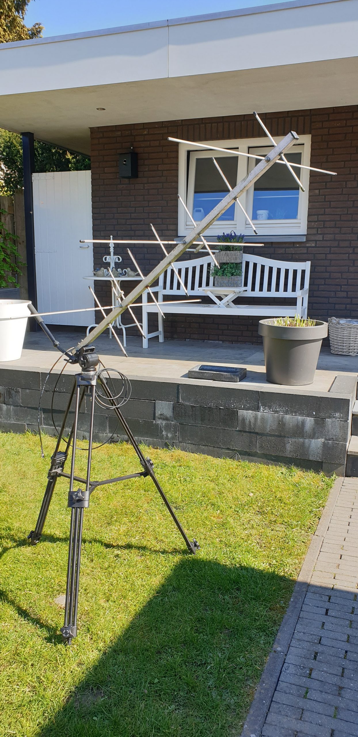 e antenne op een stevig statief te plaatsen kon deze goed worden gericht om het ISS handmatig te volgen. Het programma heeft een compasweergave waarmee je op het oog de antenne kunt richten op de juiste plek.
Deze antenne is voor zowel VHF als UHF geschikt, dat laatste is voor het ISS dus niet nodig maar wel handig voor andere satellieten. Dus wie weet wat de toekomst brengt.
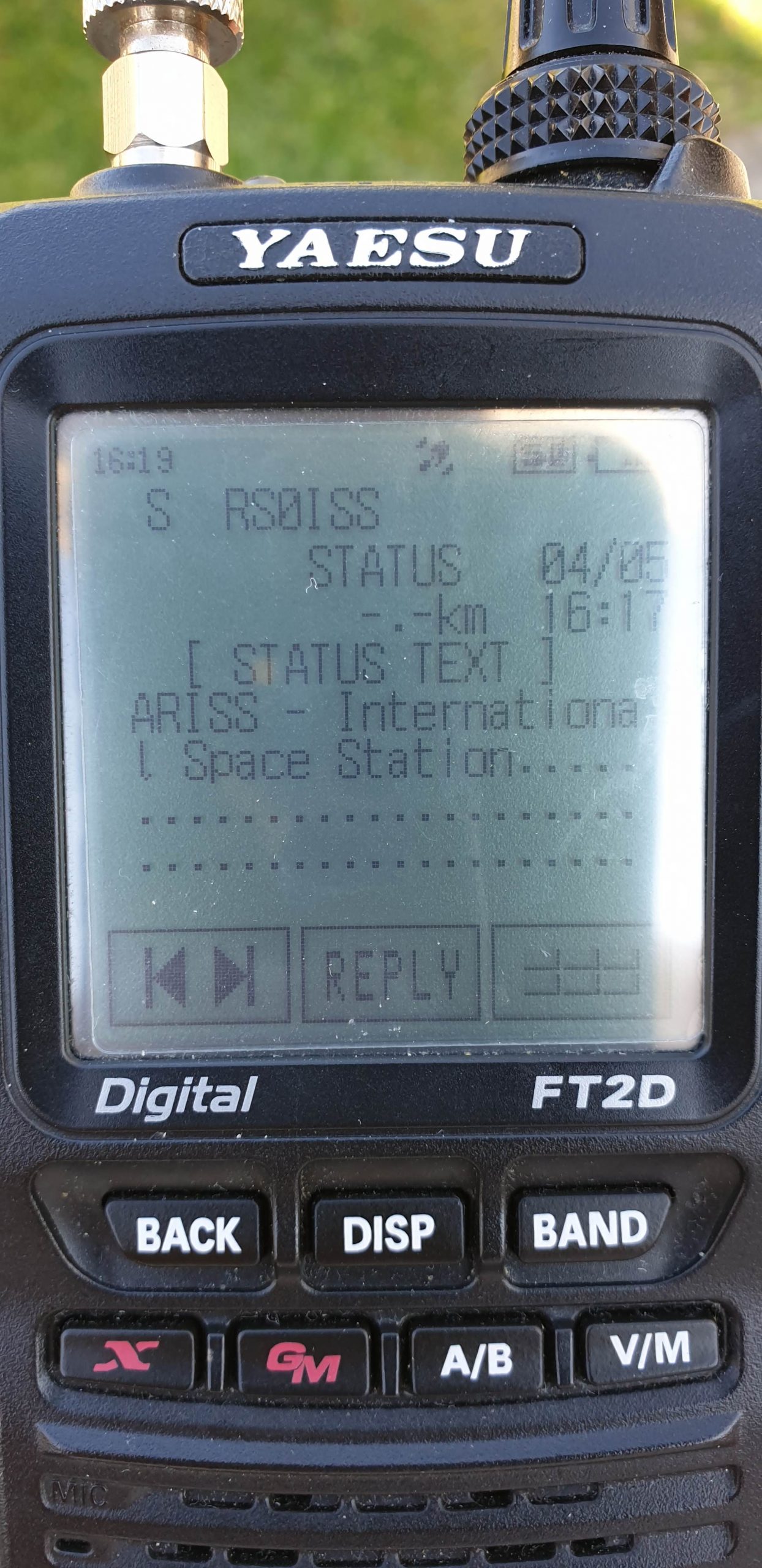 Bij de eerste pass was het meteen raak: het ISS werd ontvangen op de portofoon! Alleen was het vermogen waarschijnlijk te laag om ook door het ISS gehoord te worden. Maar de RX was in elk geval in orde.
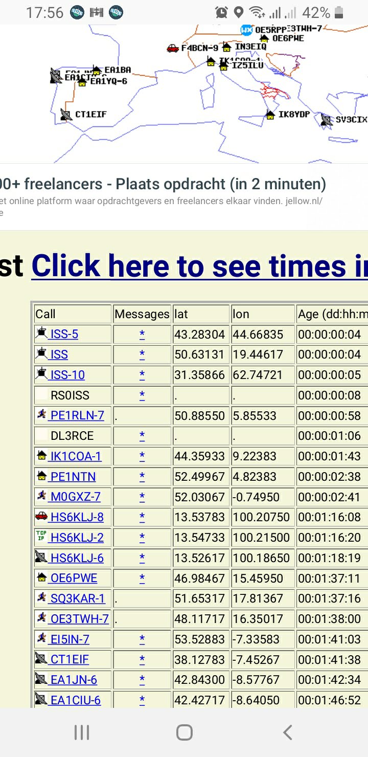
Bij de 2e pass werd meer vermogen gebruikt, 35W want je weet maar nooit. En jawel hoor: raak! Via de website van ARISS was duidelijk de logging te zien en ook via www.ariss.net kon je zien dat het baken goed werd gerelayeerd.
 De 3e pass was nog mooier want toen werd het baken door het ISS goed ontvangen, gerelayeerd en door dezelfde porto weer ontvangen en weergegeven! Hiervoor moet de antenne goed zijn gericht en moeten andere stations zich even rustig houden zodat beide uitzendingen ongestoord kunnen plaatsvinden.
Op de onderste foto 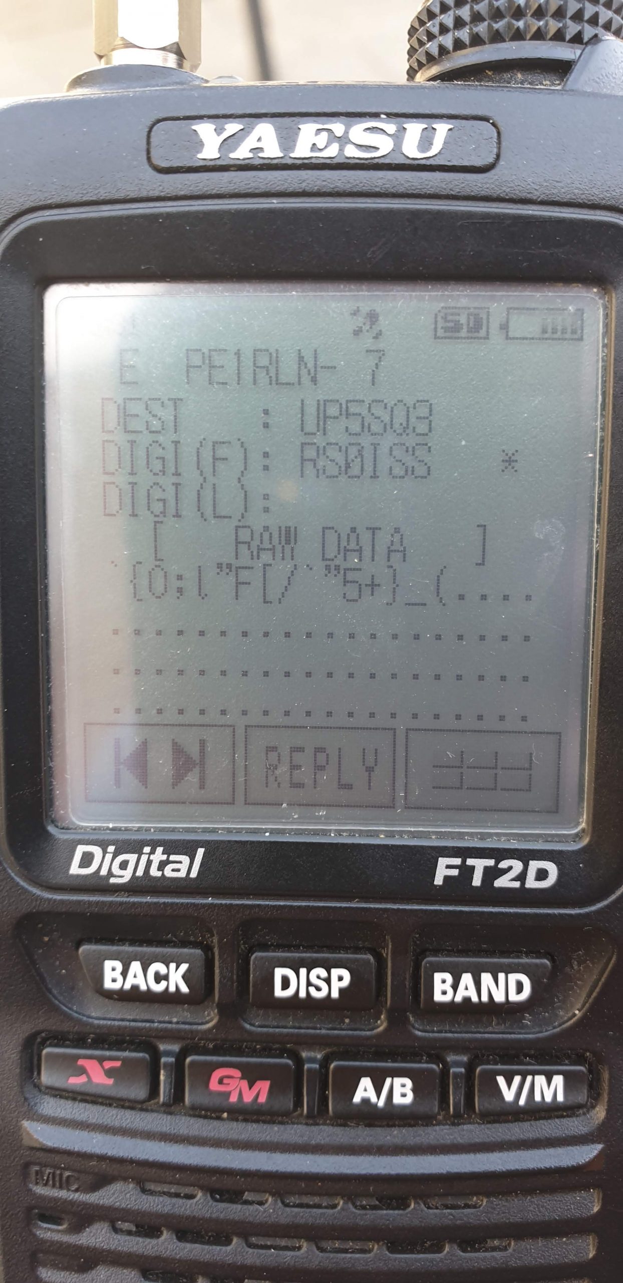 is goed te zien dat alle systemen goed funtioneren! Bij een 4e pass is dit wederom gelukt, in komende experimenten wordt gekeken of het ook met minder vermogen kan, dat zou namelijk wel moeten kunnen. Als het ISS richting het oosten beweegt, is duidelijk te merken dat er minder stations worden gehoord. Een pass uitzoeken waarbij het ISS in het oosten een wat hogere elevatie heeft (> 30 graden, boven bebouwing) zou dus gunstiger moeten uitpakken.
Al met al een goed bestede corona-zondag en zeker aanleiding om in de toekomst met minder vermogen dit QSO nog eens over te doen en ook over te stappen op andere satellieten.
Multi-Band Receiver On A Chip Controlled By Arduino
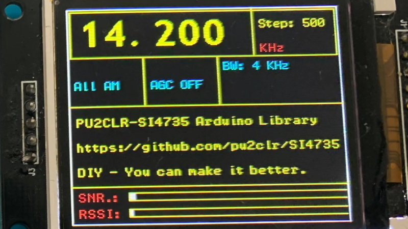
The Silicon Labs Si4735 is a single-chip solution for receiving AM, FM, and shortwave radio. With a bit of hacking, it even supports single sideband (SSB). All you’ve got to do is provide it with a suitable control interface, which [Ricardo Lima Caratti] has done with his recent project.
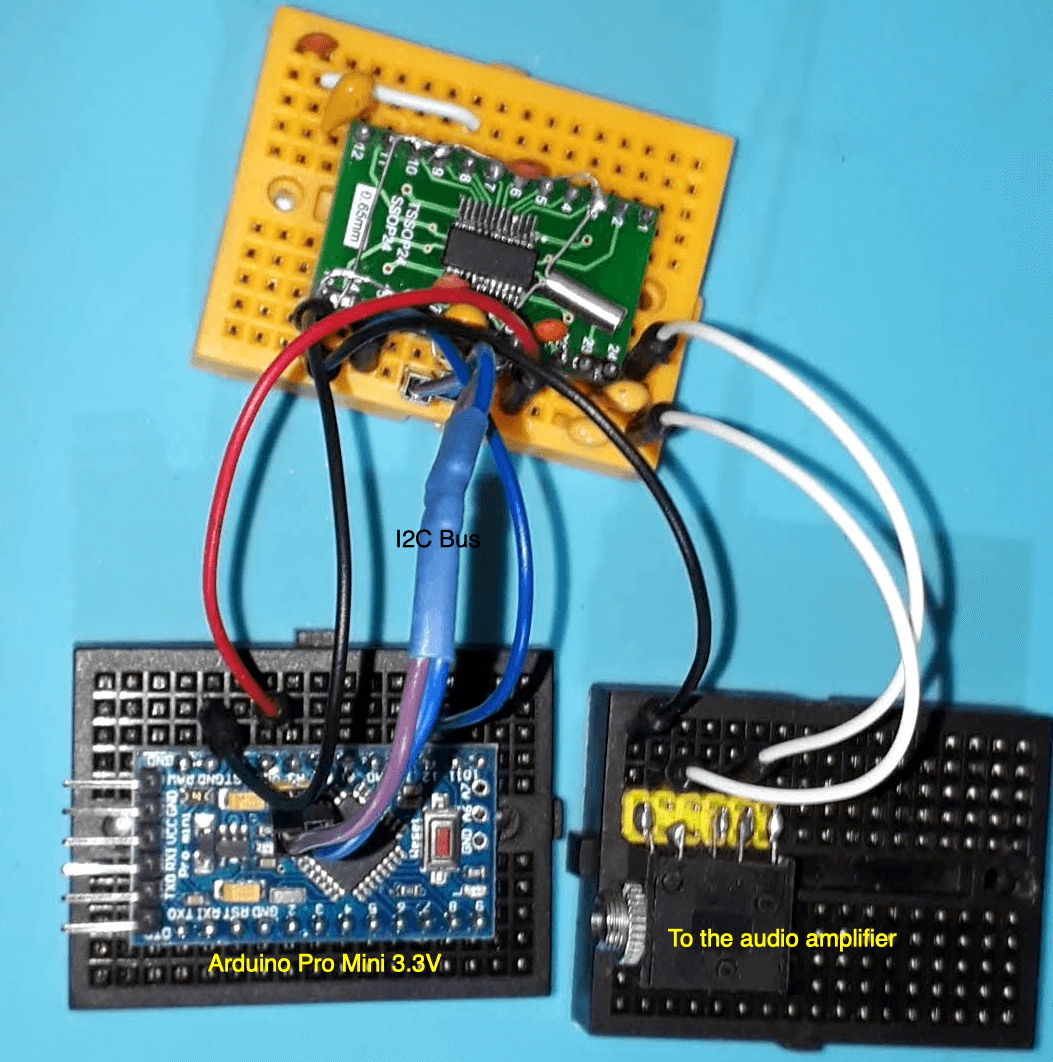 Using an Arduino Pro Mini, a handful of buttons, and a standard TFT display, [Ricardo] has put together a serviceable little receiver with a fairly impressive user interface. We especially like the horizontal bars indicating the signal to noise ratio and received signal strength. The next evolution would be to put this whole rig into some kind of enclosure, but for now he seems content to control the action with a handful of unlabeled buttons on a piece of perfboard.
Of course, the presentation of this receiver isn’t really the point; it’s more of a proof of concept. You see, [Ricardo] is the person who’s actually developed the library that allows you to control the Si4735 from your microcontroller of choice over I2C. He’s currently tested it with several members of the official (and not so official) Arduino family, as well as the ESP32.
The documentation [Ricardo] has put together for his MIT licensed Arduino Si4735 library is nothing short of phenomenal. Seriously, if all open source projects were documented even half as well as this one is, we’d all be a few notches closer to world peace. Even if you aren’t terribly interested in adding shortwave radio reception to your next project, you’ve got to browse his documentation just to see where the high water mark is.
We actually first heard about this library a few days ago when we covered another receiver using the Si4735 and [Ricardo] popped into the comments to share some of the work he’d been doing to push the state-of-the-art forward for this promising chip.
Mooie uitleg over tandwielen en overbrenging

Een interessante uitleg over hoe tandwielen nou écht werken. Klikt op het plaatje voor de link!
Ham Antennas From MIT
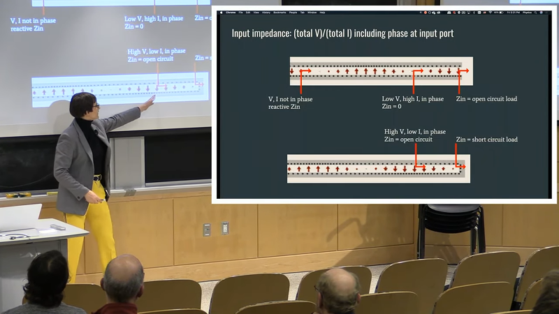
Dealing with an antenna is one of those topics we never feel like we know enough about. MIT had a live stream of [Dr. Kiersten Kerby-Patel] discussing antennas in a talk, sponsored by the ham radio club on campus. You can see the recording below.
The main assertion of the presentation is that everything is a dipole unless it is a loop. Although the professor probably deals with antennas at an extremely high theoretical level, she did a great job of keeping it aimed at ham radio operators.
The talk is about an hour long, so it isn’t optimized for the YouTube generation. There’s some introductory material that looks as though it would have been in one of our old physics classes. However, the talk gets more practical towards the end.
There’s the obligatory mention of Yagis and loops. There’s even a Smith chart. If you don’t know what the Chu limit is, you should definitely be watching this video. The end of the talk covers some very small antennas using active devices or even moving parts.
If you want more discussions on the why behind antennas, we really liked this video. This two-parter is worth your time, too.
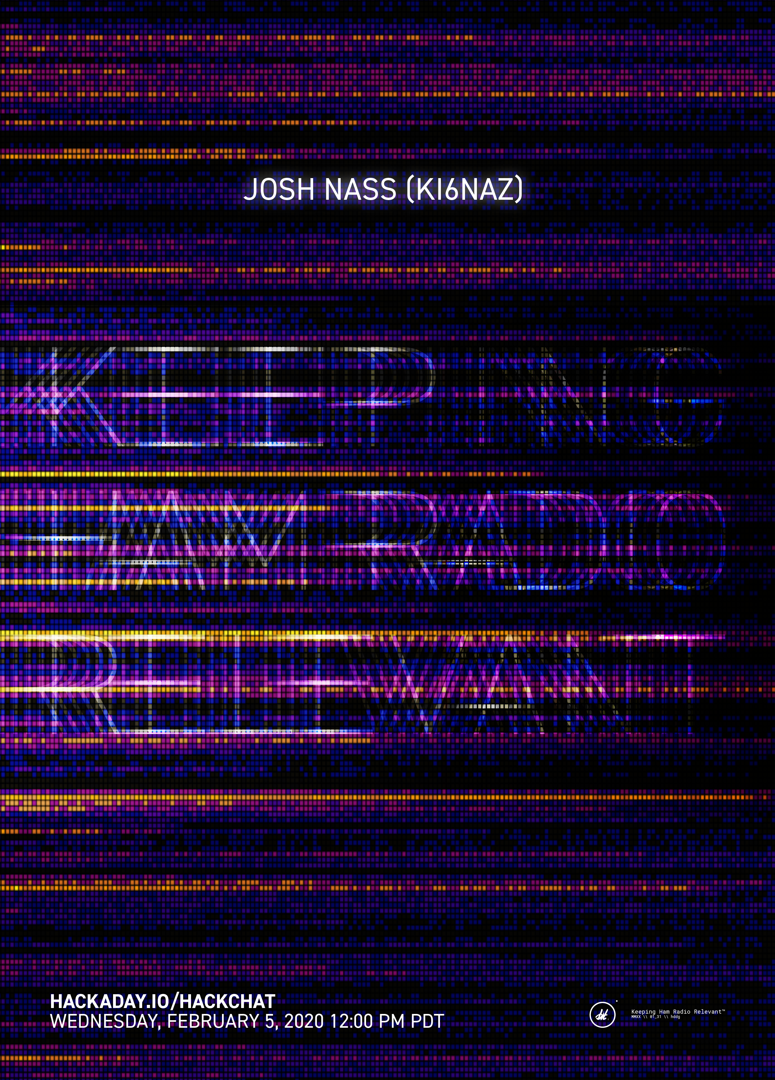
Keeping Ham Radio Relevant Hack Chat
Join us on Wednesday, February 5 at noon Pacific for the Keeping Ham Radio Relevant Hack Chat with Josh Nass!
It may not seem like it, but amateur radio is fighting a two-front war for its continued existence. On the spectrum side, hams face the constant threat that the precious scraps of spectrum that are still allocated to their use will be reclaimed and sold off to the highest bidder as new communication technologies are developed. On the demographic side, amateur radio is aging, with fewer and fewer young people interested in doing the work needed to get licensed, with fewer still having the means to get on the air.
Amateur radio has a long, rich history, but gone are the days when hams can claim their hobby is sacrosanct because it provides communications in an emergency. Resting on that particular laurel will not win the hobby new adherents or help it hold onto its spectrum allocations, so Josh Nass (KI6NAZ) is helping change the conversation. Josh is an engineer and radio amateur from Southern California who runs Ham Radio Crash Course, a YouTube channel dedicated to getting people up to speed on ham radio. Josh’s weekly livestreams and his video reviews of ham radio products and projects show a different side of the World’s Greatest Hobby, one that’s more active (through events like “Summits on the Air”) and focused on digital modes that are perhaps more interesting and accessible to new hams.
Join us on the Hack Chat as we discuss how to make ham radio matter in today’s world of pervasive technology. We’ll talk about the challenges facing amateur radio, the fun that’s still to be had on the air even when the bands are dead like they are now (spoiler alert: they’re not really), and what we can all do to keep ham radio relevant.
 Our Hack Chats are live community events in the Hackaday.io Hack Chat group messaging. This week we’ll be sitting down on Wednesday, February 5 at 12:00 PM Pacific time. If time zones have got you down, we have a handy time zone converter.
Click that speech bubble to the right, and you’ll be taken directly to the Hack Chat group on Hackaday.io. You don’t have to wait until Wednesday; join whenever you want and you can see what the community is talking about.
Machine Learning System Uses Images To Teach Itself Morse Code

Conventional wisdom holds that the best way to learn a new language is immersion: just throw someone into a situation where they have no choice, and they’ll learn by context. Militaries use immersion language instruction, as do diplomats and journalists, and apparently computers can now use it to teach themselves Morse code.
The blog entry by the delightfully callsigned [Mauri Niininen (AG1LE)] reads like a scientific paper, with good reason: [Mauri] really seems to know a thing or two about machine learning. His method uses curated training data to build a model, namely Morse snippets and their translations, as is the usual approach with such systems. But things take an unexpected turn right from the start, as [Mauri] uses a Tensorflow handwriting recognition implementation to train his model.
Using a few lines of Python, he converts short, known snippets of Morse to a grayscale image that looks a little like a barcode, with the light areas being the dits and dahs and the dark bars being silence. The first training run only resulted in about 36% accuracy, but a subsequent run with shorter snippets ended up being 99.5% accurate. The model was also able to pull Morse out of a signal with -6 dB signal-to-noise ratio, even though it had been trained with a much cleaner signal.
Other Morse decoders use lookup tables to convert sound to text, but it’s important to note that this one doesn’t. By comparing patterns to labels in the training data, it inferred what the characters mean, and essentially taught itself Morse code in about an hour. We find that fascinating, and wonder what other applications this would be good for.
Thanks to [Gordon Shephard] for the tip.
Zijn we onlangs – zonder het te beseffen – een nieuwe zonnecyclus ingerold?