The United Kingdom is somewhat unique in the world for requiring those households which view broadcast television to purchase a licence for the privilege. Initially coming into being with the Wireless Telegraphy Act in 1923, the licence was required for anyone receiving broadcast radio, before being expanded to cover television in 1946. The funds generated from this endeavour are used as the primary funding for the British Broadcasting Corporation.
Of course, it’s all well and good to require a licence, but without some manner of enforcement, the measure doesn’t have any teeth. Among other measures, the BBC have gone as far as employing special vans to hunt down illegally operating televisions and protect its precious income.
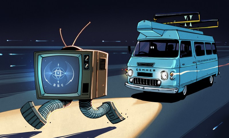
The Van Is Coming For You
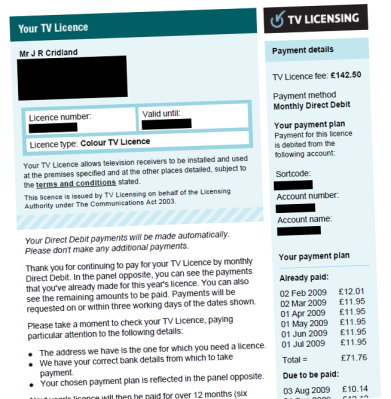
To ensure a regular income, the BBC runs enforcement operations under the TV Licencing trade name, the entity which is responsible for administering the system. Records are kept of licences and their expiry dates, and investigations are made into households suspected of owning a television who have not paid the requisite fees. To encourage compliance, TV Licencing regularly sends sternly worded letters to those who have let their licence lapse or have not purchased one. In the event this fails, they may arrange a visit from enforcement officers. These officers aren’t empowered to forcibly enter homes, so in the event a homeowner declines to cooperate with an investigation, TV Licencing will apply for a search warrant. This may be on the basis of evidence such as a satellite dish or antenna spotted on the roof of a dwelling, or a remote spied on a couch cushion through a window.
Alternatively, a search warrant may be granted on the basis of evidence gleaned from a TV detector van. Outfitted with equipment to detect a TV set in use, the vans roam the streets of the United Kingdom, often dispatched to addresses with lapsed or absent TV licences. If the van detects that a set may be operating and receiving broadcast signals, TV Licencing can apply to the court for the requisite warrant to take the investigation further. The vans are almost solely used to support warrant applications; the detection van evidence is rarely if ever used in court to prosecute a licence evader. With a warrant in hand, officers will use direct evidence such as a television found plugged into an aerial to bring an evader to justice through the courts.
Detecting Television Usage
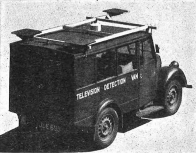
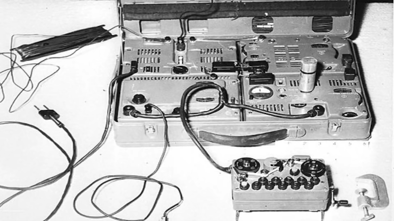
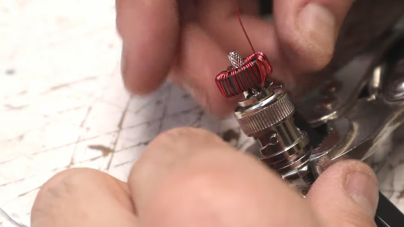
The vans were first deployed in 1952, with equipment designed to pick up the magnetic field from the horizontal deflection scanning of the picture tube, at 10.125 KHz. Loop antennas were used to detect the second harmonic of this signal at 20.25 KHz, which was mixed with a local beat frequency oscillator at 19.25 KHz to create a 1 KHz tone to indicate to the operator when a signal was picked up. Three antennas were used, one on the front of the van and two on the rear on the left and right sides. When the van was next to an operating television in a house, the signal between the front and side antenna would be roughly the same. Signal from the right and left antennas could then be compared to determine which side of the street the television was on.
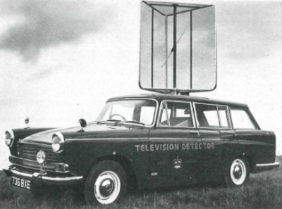
Once ITV started broadcasting in 1963, this method of detection became impractical. The two television stations did not synchronise their line-scan signals, so neighbouring houses watching different channels would create confusing interference for the detector. To get around this, the vans switched to detecting the local oscillator of the TV set’s superheterodyne VHF receiver instead. With stations broadcasting on bands spanning 47 to 240 MHz, it was impractical at the time to build a tuner and antenna to cover this entire range. Instead, the equipment was designed to work from 110-250MHz tuning in the fundamental frequencies of the higher bands, or the harmonics of the lower frequency oscillators. A highly directional antenna was used to hone in on a set, and a periscope was installed to allow the operator to view the house the antenna was pointing at. If operating in the dark, the periscope could instead be used to shine a small dot of light in the direction of the antenna’s facing, to identify the relevant target. Results were cross-referenced with a list of houses with lapsed or absent licences to help hunt down evaders.
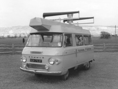
The introduction of UHF transmissions led to further redesigns. Engineers again leaned on harmonics to allow a single system to cover the full range from low VHF to higher UHF frequencies. A pair of 6′ long log-periodic spiral antennas were used, mounted on top of the van, which could be varied in spacing to effectively tune different frequencies. In practice, the antennas would be pointed towards a row of houses, while the van was slowly driven along the street. The beam pattern of the antenna pair would show seven distinct lobes on a CRT inside the van when a TV was detected. An operator would press a button to mark house boundaries on the CRT as the van moved, and when the lobe pattern centered on a particular house, the TVs location was clear. The hardware was further refined over the years, with various antenna rigs and detection equipment used as technology marched on.
Seeking Television in Modern Times

Modern efforts to detect licence evasion are shrouded in mystery. Modern flatscreen displays receiving digital television signals do not emit as much radio frequency interference as older designs, and any such signals detected are less easily correlated with broadcast television. An LCD television in the home can just as easily be displaying output from a video game console or an online streaming service, with both being usage cases that do not require the owner to pay a licence fee. Based on an alleged BBC submission for a search warrant in recent years, there may be optical methods used in which reflected light from a television in a viewer’s home is compared to a live broadcast signal. The BBC declined to answer the Freedom of Information request with any details of their methods, other than to say they have employed vehicles and handheld devices in enforcement efforts. However, given the multitude of broadcast, cable and satellite channels now available, the comparison effort would necessarily be much harder, leading some to suspect the days of the detector van are largely over.
While the TV licence may have its days numbered with the increased dominance of streaming content, it remains a quirky piece of legislation that spawned the development of a technical curiosity. If you fancy yourself a television sleuth, sound off in the comments with your chosen approach to hunting for televisions watching broadcast content illegally in this modern era. And be sure to look over your shoulder – you never know when TV Licencing might be knocking on your door!
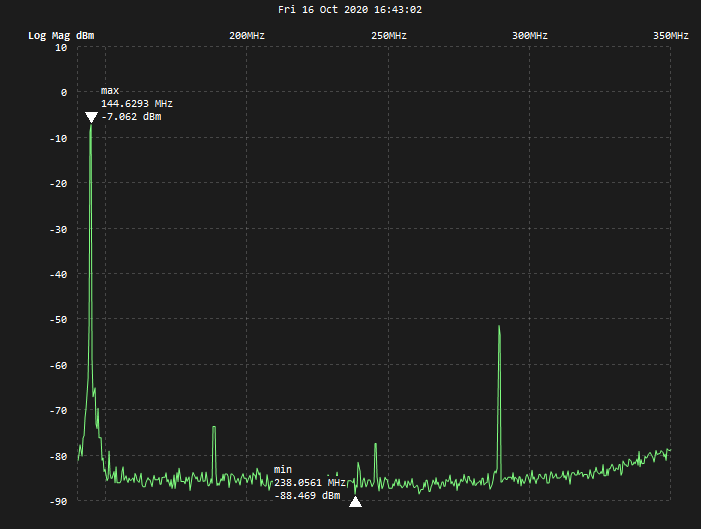
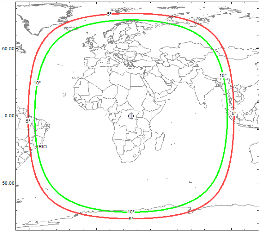
 De bias-tee komt dus tussen LNB en ontvanger (tenzij je ontvanger al 12V op de coax heeft) en dan stem je af op 432,750 MHz.
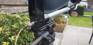
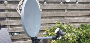 Stel de schotel bijna vertikaal en richt de arm van de LNB richting het zuiden. Draai vervolgens 26 graden naar het oosten (tegen wijzers van de klok in dus).
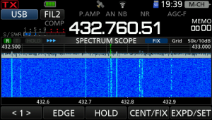 De signalen zijn zeer goed te nemen, alsof het lokale SSB signalen zijn.