As any radio amateur will tell you, the world of radio abounds with exciting possibilities. Probably the simplest pursuit of them all is that of the SWL, or short wave listener, who scours the airwaves in search of interesting stations. SWLs will often have fully-featured setups with high-end general-coverage communications receivers and tuned antenna arrays, but it can start with the cheapest of radios at its bottom end. Such a radio is the subject of this review, the XHDATA D-219 is a miniature portable receiver that costs under ten dollars, yet is currently the talk of the town in SWL circles. This interest is in no small amount due to its being an especially low-price way to get your hands on a shortwave radio using one of the SIlicon Labs integrated software-defind radio receiver chips. We don’t often review a consumer radio here at Hackaday, but with an avid eye for unexpected gems at the cheaper end of the market this one’s worth a second look.
What Do You Get For Your Tenner?
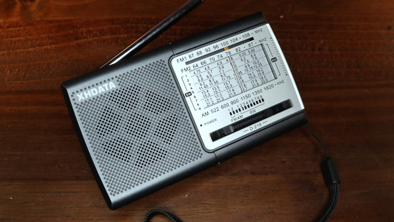
I ordered my D-219 from the XHDATA website, spending about £10 including the postage from China. The usual wait ensued before the package landed on my doormat, and inside was the radio in its box with an instruction leaflet. It’s a small unit about 135 mm x 75 mm x 30 mm, and it follows closely the form factor of other similar radios.
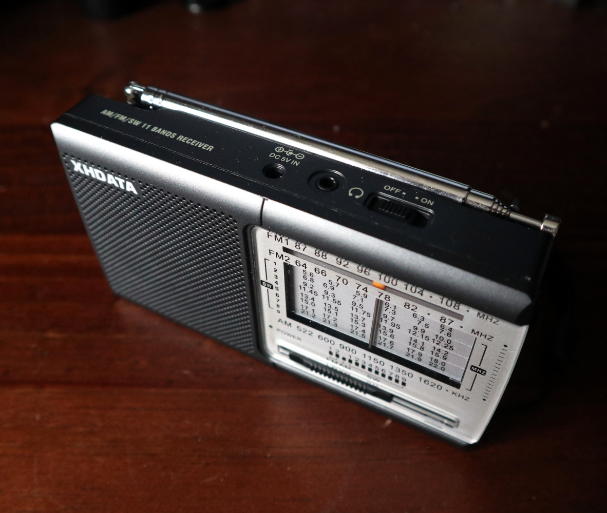
On the top is the extensible antenna with an on-off switch and sockets for headphone and 5 V power, on the side are side-on knobs for tuning and volume, while on the front is the speaker and old-style multi-band tuning display.
On the back is a flip-up stand and a hatch for a pair of AA cells. There’s a band switch covering AM, nine different shortwave bands from 4.75 MHz to 22 MHz, the east Asian FM band from 64 MHz to 87 MHz, and the international FM band from 87 MHz to 108 MHz. The tuning indicator is very old-school, a vertical bar that moves across a frequency scale with the tuning knob.
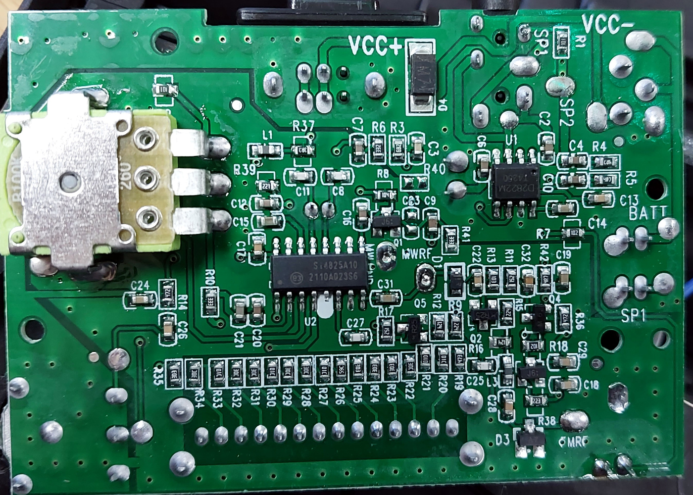
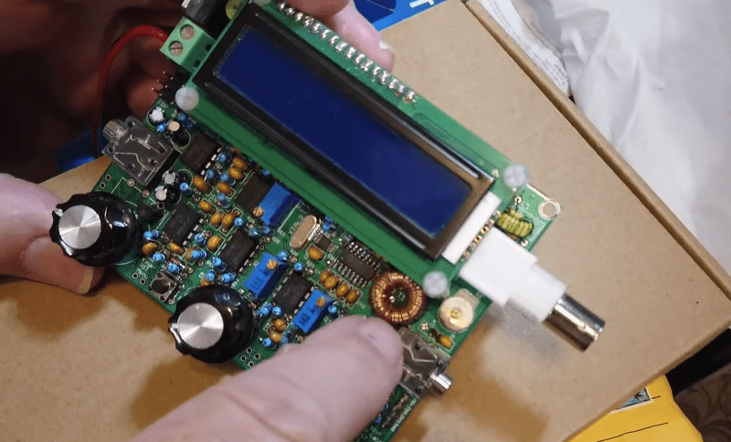
Opening it up, and it’s immediately obvious how simple the DSP chip makes a radio like this. Where once you’d have seen a board covered in analogue circuitry taking up most of the space, now aside from the AM ferrite rod antenna there’s a board about a third the size of the case, behind the tuning display. Carefully lifting this up reveals the circuitry, all surface-mount, with a Silicon Labs Si4825 single-chip DSP radio, and a Shaoxing Silicore D2882 audio amplifier being the only integrated circuits.
How Does It Compare To Older Cheap Radios?
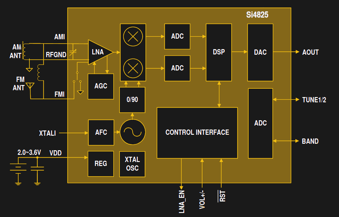
The Silicon Labs single-chip radios are nothing new, having been on the market for over a decade. They come in a wide variety of versions for different applications and control methods, with the Si4825 being one of the lower-end versions. In keeping with its traditional analogue interface it doesn’t have any digital controls, instead it achieves both tuning and band switching by means of voltage. A switched voltage divider selects the band, while a variable resistor serves as the tuning control. Some of the higher-spec chips in the series allow the insertion of DSP code to demodulate for example SSB signals, but this one remains firmly stuck with AM, and FM on the two VHF bands. Inserting some batteries and turning it on, and there were the usual dial-full of FM stations. The real action though lies in the shortwave bands, so that was where I headed next. And immediately I had in my headphones a world of stations, and while the shortwave bands have seen a decline since I first listened to them back in the 1980s, there were still enough for me to quickly identify stations from the far east, north America, the Arabic-speaking world, and from eastern Europe.
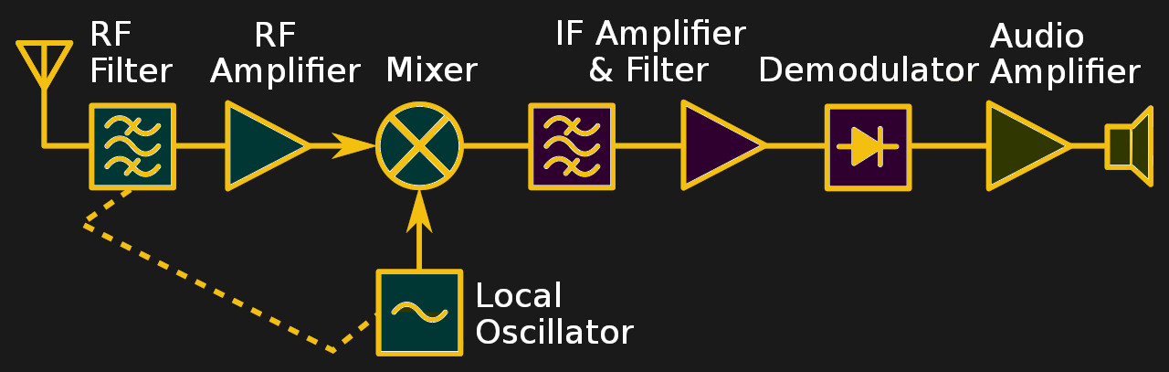
When evaluating a small portable shortwave radio like this one it’s important to understand a little about how such radios have traditionally worked. My other older cheap radio with a few shortwave bands is a more conventional model, it has a tuning capacitor that controls both an input tuned circuit and an oscillator. The oscillator is set 455 kHz away from the desired station, and the signal from the antenna is mixed with it to create a so-called intermediate frequency, the difference between the two at 455 kHz. This is then fed into an IF amplifier tuned to 455 kHz from which the audio can be demodulated.
It has two major shortcomings, first that 455 kHz isn’t enough distance from the receive frequency in a cheap shortwave radio, and second that the bandwidth of that 455 kHz amplifier is quite wide. The first leaves the possibility of receiving whatever is on the sum of the oscillator and 455 kHz alongside its difference, while the second sets the slice of spectrum that you are listening wide enough that more than one station can be heard at once. More expensive traditional receivers like my workhorse 1980s Lowe solve this by using a much larger frequency difference than 455 kHz and some expensive filter components to reduce that bandwidth, but you would certainly find neither in a ten dollar radio. The experience of short wave listening on a very cheap radio has thus always been rather dismal. Tuning is difficult, and there is lots of interference and breakthrough from other stations.
How Good is It And Should You Buy It?
A radio based on one of these Silicon Labs chips immediately solves both of the problems from the previous paragraph due to its software-defined architecture: it has no IF offset to worry about, and it replaces the need for those expensive filters by means of signal processing in its software. Thus the effect is much more similar to that of a receiver with one of those expensive IF filters: there’s little or no breakthrough from all those adjacent stations, and tuning becomes much easier. It also seems as though the demodulator is better than its analogue equivalent, returning even weak signals in a much clearer form. How much of this is my imagination and how much DSP tricks I can’t tell you, but the radio certainly delivers.
To sum up the D-219 then, it’s a good little radio that gives good results for a pocket-money price, and I can see why the SWL community are rather excited about it. It will never equal a high-end general coverage receiver with a well-implemented antenna array and even the Silicon Labs SDR chip is not new, but for the price of a couple of pints of beer it’s a no-brainer and a diamond in the rough.
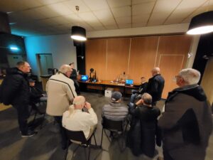 Op vrijdag 24 februari gaf Jeffrey PD1NL samen met zijn zoon Joey een lezing en demonstratie over 3d printers. Allerlei facetten kwamen voorbij zoals materiaalkeuze, ontwerp, software, printers en natuurlijk een demonstratie.
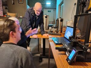

 Onlangs bereikte ons het droevige bericht dat PDØHCE (Huub Kuijen) op 69-jarige leeftijd is overleden.