 In verband met carnaval is er op 11 en 18 februari geen bijeenkomst in Spaubeek.
Aan alle carnavalsvierders: een fijne carnaval gewenst!
In verband met carnaval is er op 11 en 18 februari geen bijeenkomst in Spaubeek.
Aan alle carnavalsvierders: een fijne carnaval gewenst!
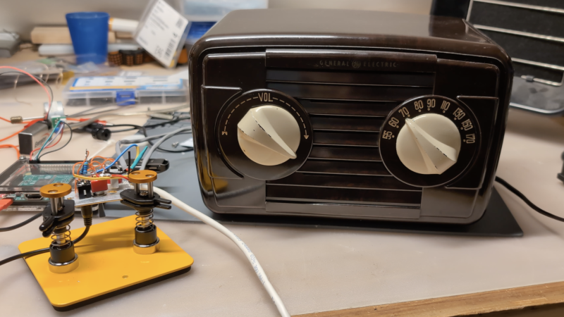
Although we do often see projects that take antiques and replace some or all of their components with modern equipment, we can also sympathize with the view that (when possible and practical) certain antique electronics should be restored rather than gutted. [David] has this inclination for his 1948 GE radio, but there are a few issues with it that prevented a complete, period-correct restoration.
The main (pun intended) issue at the start of this project was safety. The original radio had a chassis that was just as likely as not to become energized, with the only protection being the plastic housing. [David] set up an isolation transformer with a modern polarized power cable to help solve this issue, and then got to work replacing ancient capacitors. With a few other minor issues squared away this is all it took to get the radio working to receive AM radio, and he also was able to make a small modification to allow the radio to accept audio via a 3.5mm jack as well.
However, [David] also has the view that a period-correct AM transmission should accompany this radio as well and set about with the second bit of this project. It’s an adaptation of a project called FieldStation42 originally meant to replicate the experience of cable TV, but [Shane], the project’s creator, helped [David] get it set up for audio as well. A notable feature of this system is that when the user tunes away from one station, it isn’t simply paused, but instead allowed to continue playing as if real time is passing in the simulated radio world.
Although there are a few modern conveniences here for safety and for period-correct immersion, we think this project really hits the nail on the head for preserving everything possible while not rolling the dice with 40s-era safety standards. There’s also a GitHub page with some more info that [David] hopes to add to in the near future. This restoration of a radio only one year newer has a similar feel, and there are also guides for a more broad category of radio restorations as well.
 Tijdens de ALV van dinsdag 20 januari hebben de aanwezige leden unaniem ingestemd met de installatie van een deels nieuw bestuur:
Voorzitter: Thijs Has PE1RLN
Penningmeester: Mark Vroomen PC9DB
Secretaris: Thijs Has PE1RLN a.i.
Het nieuwe bestuur benadrukt dat ze het komende jaar zelf NIETS zullen doen aan huisvesting, bijeenkomsten en activiteiten, dat komt volledig voor rekening van de leden. Het bestuur zal alle initiatieven faciliteren, waar nodig begeleiden en financieren en indien noodzakelijk geacht een bijzondere ledenvergadering bijeenroepen (bijvoorbeeld bij het bepalen van een nieuwe locatie).
Het bestuur is bereikbaar via de mailadressen en natuurlijk op de clubavonden.
LET OP HET IS NIET IN SPAUBEEK MAAR IN HET WEVERKE TE SCHIMMERT
Hierbij nodig ik namens het bestuur alle leden van de afdeling uit voor het bijwonen van de Algemene Ledenvergadering (ALV) die zal worden gehouden op dinsdag 20 januari 2026 om 20:00 uur in Het Weverke, Hoofdstraat 77, 6333 BG, Schimmert.
Aftredend bestuur en eventuele opheffing van de afdeling
Vorig jaar januari is de afdeling “gered”. Er waren geen kandidaten voor een bestuursfunctie, maar tijdens de vergadering bleken uiteindelijk drie leden bereid om een bestuur te vormen. Voor alle drie gold – samengevat – dat zij hun taak als voorwaardelijk zagen en wilden zien hoe het zou gaan verlopen.
Het bestuur heeft het afgelopen jaar geëvalueerd en is tot de conclusie gekomen dat het gebrek aan belangstelling voor activiteiten niet is veranderd, nog daargelaten de bereidheid van leden om activiteiten te organiseren of daarbij mee te helpen. De wekelijkse bijeenkomsten worden weliswaar bezocht, maar in de praktijk komt het erop neer dat het niet uitmaakt of er een bestuur is of niet.
Daarom hebben Guido, PA4GR, Mark, PC9DB en Henk, PA2S besloten af te treden en zich niet herkiesbaar te stellen.
Wanneer zich geen opvolgers melden, zal het huidige bestuur besluiten om de afdeling op te heffen. Als er geen voortzetting mogelijk is, zal in een aparte vergadering eind februari of begin maart het definitieve besluit daartoe moeten worden genomen. Daarbij zal onder andere ook beslist worden over de bestemming van het batig saldo.
Een en ander leidt tot de volgende agenda:
1. Opening door de voorzitter met terugblik 2025
2. Verslag van de penningmeester
3. Verslag van de kascontrolecommissie
4. Aftreden en eventueel verkiezen nieuw bestuur
5. Afhankelijk van punt 4 besluit over vervolgstappen.
Deelnemers moeten een geldig lidmaatschap hebben en de presentielijst tekenen.
Wij streven ernaar om uiterlijk het komende weekeinde vergaderstukken toe te zenden.
Wij rekenen op uw komst!
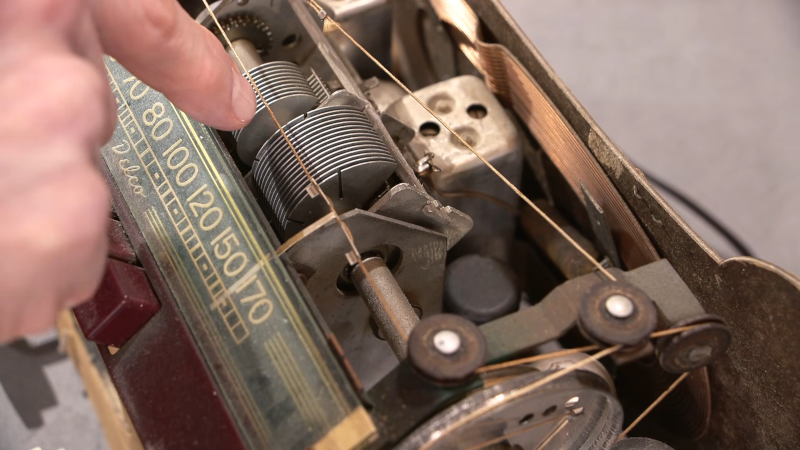
If you’ve seen a big air-variable capacitor, you may have noticed that some of the plates may have slots cut into them. Why? [Mr Carlson] has the answer in the video below. The short answer: you can bend the tabs formed by the slots to increase or decrease the capacitance by tiny amounts for the purpose of tuning.
For example, if you have a radio receiver with a dial, you can adjust the capacitor to make certain spots on the dial have an exact frequency. Obviously, you can only adjust in bands depending on how many slots are in the capacitor. Sometimes the adjustments aren’t setting the oscillator’s frequency. For example, the Delco radio he shows uses the capacitor to peak the tuning at the specified frequency.
You usually only find the slots on the end plates and, as you can see in the video, not all capacitors have the slots. Of course, bending the plates with or without slots will make things change. Just don’t bend enough to short to an adjacent plate or the fixed plates when the capacitor meshes.
Of course, not all variable capacitors have this same design. We’ve seen a lot of strange set ups.
Hou 20 januari vrij in jullie agenda, dan is namelijk de jaarvergadering van de afdeling.
Meer info volgt.
Via deze weg willen wij graag onder de aandacht brengen dat op dinsdag 9 december de laatste afdelingsbijeenkomst van 2025 gehouden zal worden.
Vanaf dinsdag 6 januari 2026 zullen de afdelingsbijeenkomsten weer hervatten, zoals gebruikelijk vanaf 20:00 bij Eetcafé Spech in Spaubeek.
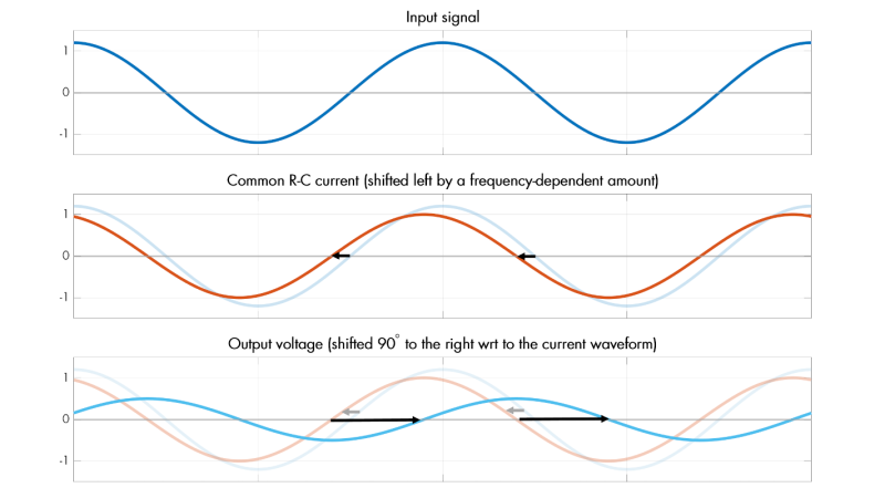
One of the major difficulties in studying electricity, especially when compared to many other physical phenomena, is that it cannot be observed directly by human senses. We can manipulate it to perform various tasks and see its effects indirectly, like the ionized channels formed during lightning strikes or the resistive heating of objects, but its underlying behavior is largely hidden from view. Even mathematical descriptions can quickly become complex and counter-intuitive, obscured behind layers of math and theory. Still, [lcamtuf] has made some strides in demystifying aspects of electricity in this introduction to analog filters.
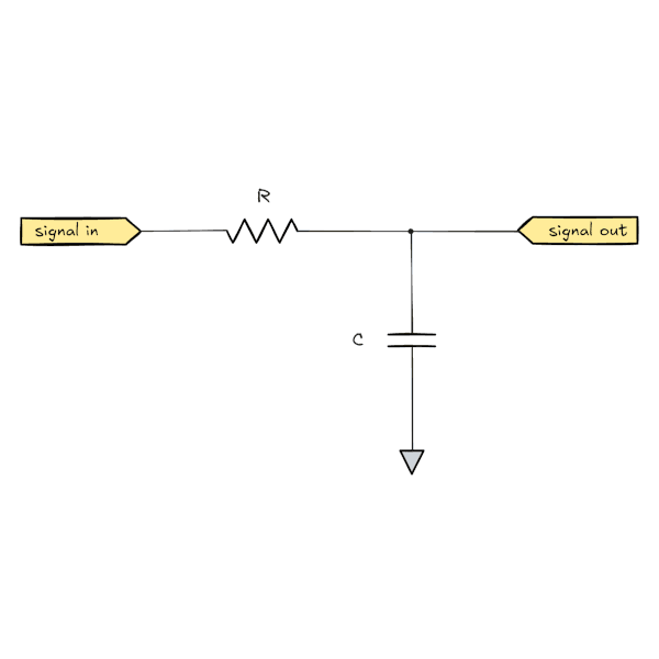 The discussion on analog filters looks at a few straightforward examples first. Starting with an resistor-capacitor (RC) filter, [lcamtuf] explains it by breaking its behavior down into steps of how the circuit behaves over time. Starting with a DC source and no load, and then removing the resistor to show just the behavior of a capacitor, shows the basics of this circuit from various perspectives. From there it moves into how it behaves when exposed to a sine wave instead of a DC source, which is key to understanding its behavior in arbitrary analog environments such as those involved in audio applications.
There’s some math underlying all of these explanations, of course, but it’s not overwhelming like a third-year electrical engineering course might be. For anyone looking to get into signal processing or even just building a really nice set of speakers for their home theater, this is an excellent primer. We’ve seen some other demonstrations of filtering data as well, like this one which demonstrates basic filtering using a microcontroller.
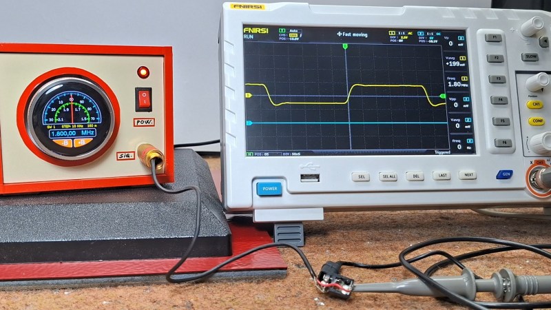
Not every project has to be complicated– reinventing the wheel has its place, but sometimes you find a module or two that does exactly what you want, and the project is more than halfway done. That the kind of project [mircemk]’s Simple Retro Style VFO is — it’s a variable frequency oscillator for HAM and other use, built with just a couple of modules.
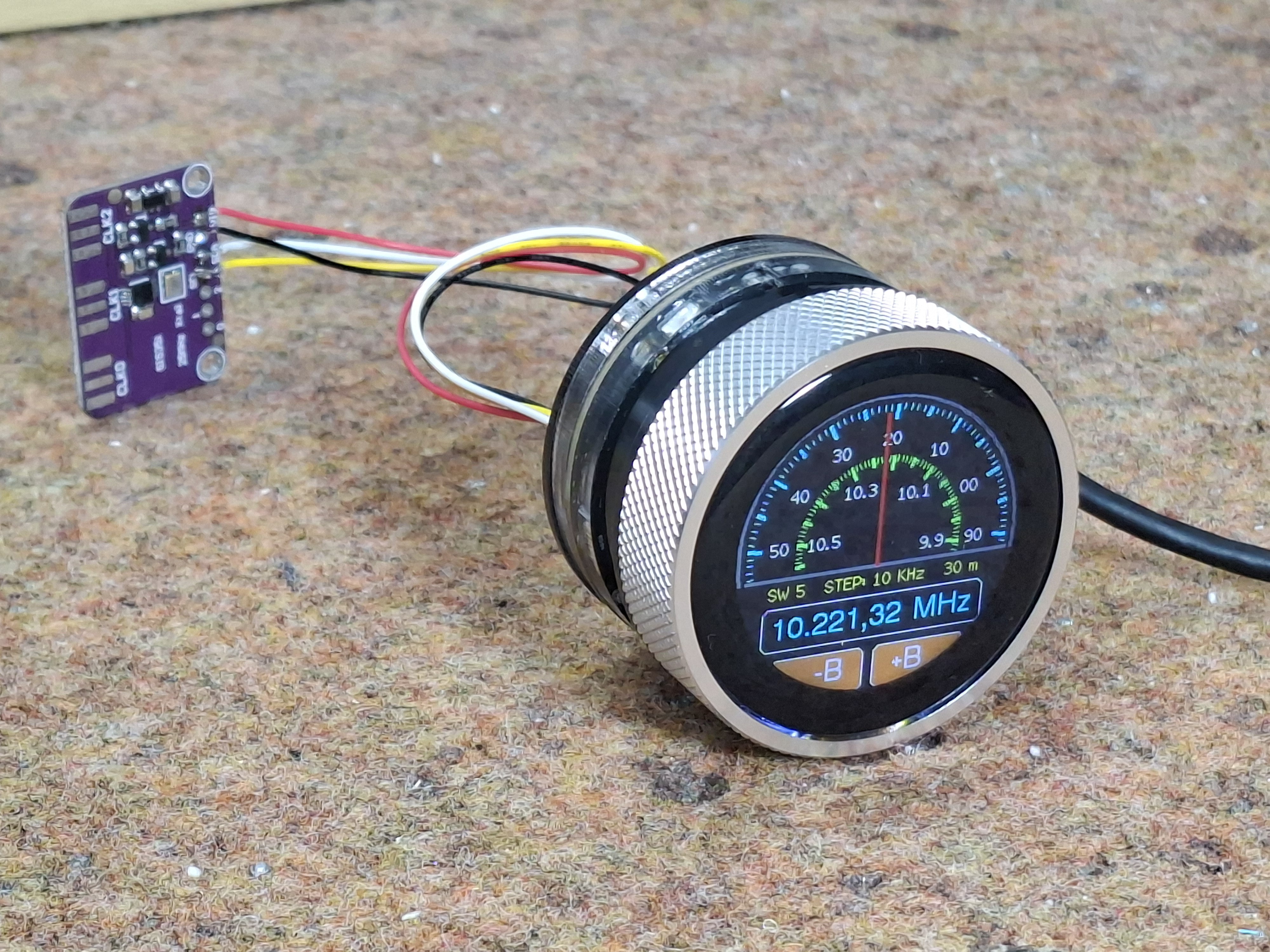
The modules in question are the SI5351 Clock Generator module, which is a handy bit of kit with its own crystal reference and PLL to generate frequencies up to 150 MHz, and the Elecrow CrowPanel 1.28inch-HMI ESP32 Rotary Display. The ESP32 in the CrowPanel controls the SI5351 module via I2C; control is via the rest of the CrowPanel module. This Rotary Display is a circular touchscreen surrounded by a rotary display, so [mircmk] has all the inputs he needs to control the VFO.
To round out the parts count, he adds an appropriate connector, plus a power switch, red LED and a lithium battery. One could include a battery charger module as well, but [mircmk] didn’t have one on hand. Even if he had, that still keeps the parts count well inside the single digits. If you like video, we’ve embedded his about the project below; if not the write up on Hackaday.io is upto [mircmk]’s typical standard.
People have been using the SI5351 to make VFOs for years now, but the addition of the round display makes for a delightfully retro presentation.
Thanks to [mircmk] for the tip.
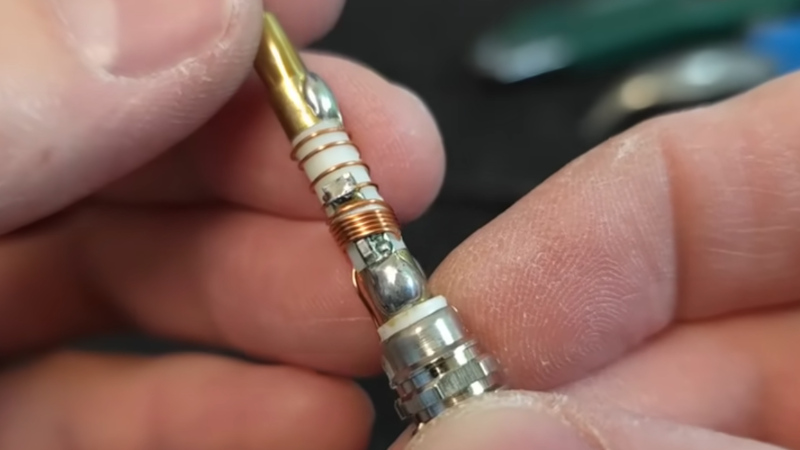
If you own a handheld transceiver of any type then the chances are it will come with a “rubber duck” style antenna. These flexible rubber-coated antennas are a compromise in performance, being significantly smaller than a wavelength at their frequency of operation. [OM40ET] has an interesting video in which he investigates this by tearing down a cheap rubber duck antenna and an even cheaper fake.
These antennas usually have a flexible upper section and a bulge at the bottom over the connector. The fake one has nothing in the bulge except the antenna wire and thus has a very high SWR, while the “real” one has a loading coil. This coil is an interesting design, because it’s designed such that the antenna has two resonant points at the 2 metre and 70 centimetre amateur bands. On paper it’s a tapped coil fed at the tap through a capacitor for matching, but a more detailed appraisal will tell you that the two halves of the coil are designed to return those two resonances. It’s still a not-very-good antenna, but the fact that it works at all is something.
If you want something better at VHF and haven’t got much space, all is not lost. We recently featured a VHF magnetic loop.