Beste leden, in de maanden juli en augustus is Eetcafé Spech op dinsdag gesloten en vinden er dus GEEN bijeenkomsten plaats. Op dinsdag 1 september is de eerstvolgende bijeenkomst!
Beste leden, in de maanden juli en augustus is Eetcafé Spech op dinsdag gesloten en vinden er dus GEEN bijeenkomsten plaats. Op dinsdag 1 september is de eerstvolgende bijeenkomst!
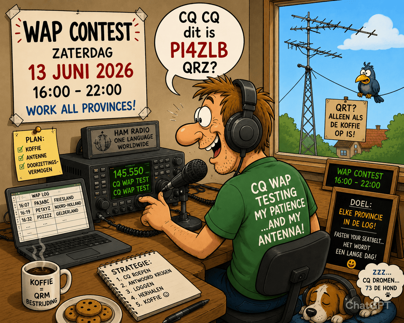 Op zaterdag 13 juni is weer de jaarlijkse Worked All Provinces contest! Vanaf 16 uur ’s middags tot 22 uur ’s avonds zijn de clubstations van de VRZA in de lucht op 6m, 4m, 2m en 70cm en zelfs hoger.
De VRZA Zuid-Limburg is natuurlijk ook van de partij en is te werken op de volgende banden:
– 6m
– 2m (SSB en PI3ZLB)
– 70cm (SSB en ON0LB)
– 2.4/10GHZ via de QO-100
Maak verbinding met zoveel mogelijk provincies en sleep die award in de wacht!
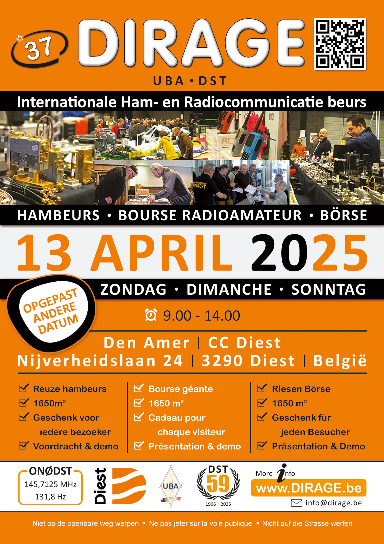
DIRAGE staat voor DIesters RAdio GEbeuren. Onder deze benaming organiseert UBA-DST sinds 1986 haar jaarlijkse beurs voor radioamateurs waar zowel tweedehands- als nieuw materiaal voor radioamateurs te koop wordt aangeboden. In de beginjaren was DIRAGE een sterk lokaal gericht evenement waar vooral de clubleden hun overbodig geworden hammateriaal probeerden kwijt te geraken, we waren toen al tevreden met een honderdtal bezoekers. De voortdurende groei van zowel de hoeveelheid materiaal als het bezoekersaantal dwong ons om meerdere malen naar een grotere lokatie te verhuizen, tot we in 2007 tot de vaststelling kwamen dat Diest te klein geworden was voor ons evenement.
De verhuis in 2008 naar een moderne en ruime lokatie was voor UBA-DST meteen ook een uitnodiging om van het oude, vertrouwde concept van DIRAGE af te stappen en onze hambeurs frisser en aantrekkelijker te maken.
Een grotere diversiteit van het aangeboden tweedehands materiaal, een uitgebreid gamma van nieuwe amateurtoestellen en antennes, de kans om tijdens een voordracht met demonstratie een nieuwe mode/materiaal van onze hobby te leren kennen, alsook het feit dat we aanverwante hobby’s de kans geven zich te tonen …. maken dat DIRAGE een begrip geworden is in ON en de place to be is voor een breed radioamateur publiek.
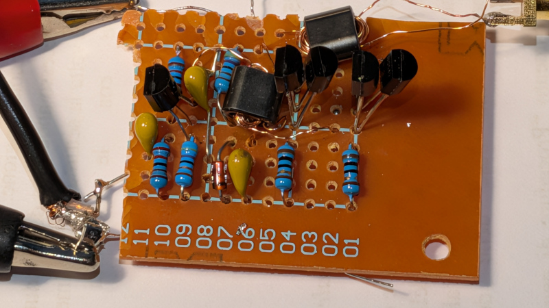
When building a radio transmitter, unless it’s a very small one indeed, there’s a need for an amplifier before the antenna. This is usually referred to as the power amplifier, or PA. How big your PA is depends on your idea of power, but at the lower end of the power scale a PA can be quite modest. QRP, as lowe power radio is referred to, has a transmit power in the miliwatts or single figure watts. [Guido] is here with a QRP PA that delivers about a watt from 1 to 30 MHz, is made from readily available parts, and costs very little.
Inspired by a circuit from [Harry Lythall], the prototype is built on a piece of stripboard. It’s getting away with using those cheap transistors without heatsinking because it’s a class C design. In other words, it’s in no way linear; instead it’s efficient, but creates harmonics and can’t be used for all modes of transmission. This PA will need a low-pass filter to avoid spraying the airwaves with spurious emissions, and on the bands it’s designed for, is for CW, or Morse, only.
We like it though, as it’s proof that building radios can still be done without a large bank balance. Meanwhile if the world of QRP interests you, it’s something we have explored in the past.
[Yeckel] recently put the finishing touches on an ambitious implementation of a simple D-STAR (Digital Smart Technologies for Amateur Radio) transceiver using some very accessible and affordable hardware. The project is D-StarBeacon, and [Yeckel] shows it working on a LilyGO TTGO T-Beam, an ESP32-based development board that includes a SX1278 radio module and GPS receiver. It even serves a web interface for easy configuration.
What is D-STAR? It’s a protocol used by radio operators for voice that also allows transmitting low-speed data, such as short text messages or GPS coordinates. While voice is out of scope for [Yeckel]’s project (more on that in a moment) it can do all the rest, including send images. That makes beacon-type functions possible on inexpensive hardware, instead of requiring a full-blown radio.
As mentioned, voice is a big part of D-STAR. While [Yeckel] was able to access the voice data, attempts to decode it were unsuccessful. A valiant effort, but we suppose voice decoding isn’t terribly relevant to beacon-type operations like transmitting APRS (Automatic Packet Reporting System).
So far as [Yeckel] is aware, D-StarBeacon is currently the only open-source implementation of a D-STAR radio available on the internet, which is pretty interesting. We’ve seen projects that touch indirectly on D-STAR, but nothing like this.
Watch it go through its paces in the video embedded below. Since the T-Beam is just a microcontroller development board, the user interface comes from an Android app on a mobile phone, which is why you see a phone in the video.
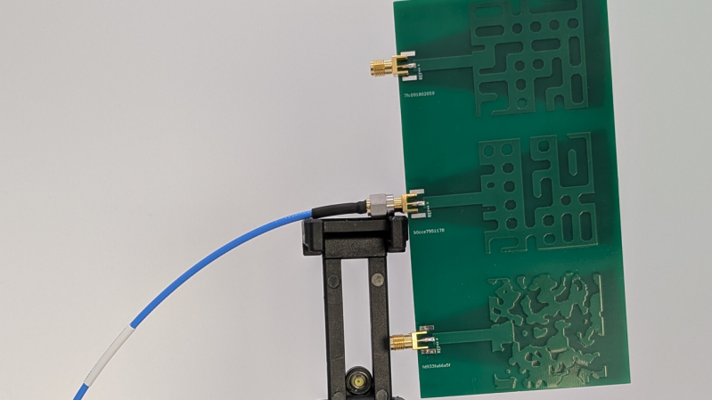
Antenna design is often referred to as a black art or witchcraft, even by those experienced in the space. To that end, [Janne] wondered—could years of honed skill be replaced by bruteforcing the problem with the aid of some GPUs? Iterative experiments ensued.
[Janne]’s experience in antenna design was virtually non-existent prior to starting, having a VNA on hand but no other knowledge of the craft. Formerly, this was worked around by simply copying vendor reference designs when putting antennas on PCBs. However, knowing that sometimes a need for something specific arises, they wanted a tool that could help in these regards.
The root of the project came from a research paper using an FDTD tool running on GPUs to inversely design photonic nanostructures. Since light is just another form of radio frequency energy, [Janne] realized this could be tweaked into service as an RF antenna design tool. The core simulation engine of the FDTD tool, along with its gradient solver, were hammered into working as an antenna simulator, with [Janne] using LLMs to also tack on a validation system using openEMS, an open-source electromagnetic field solver. The aim was to ensure the results had some validity to real-world physics, particularly important given [Janne] left most of the coding up to large language models. A reward function development system was then implemented to create antenna designs, rank them on fitness, and then iterate further.
The designs produced by this arcane system are… a little odd, and perhaps not what a human might have created. They also didn’t particularly impress in the performance stakes when [Janne] produced a few on real PCBs. However, they do more-or-less line up with their predicted modelled performance, which was promising. Code is on Github if you want to dive into experimenting yourself. Experienced hands may like to explore the nitty gritty details to see if the LLMs got the basics right.
We’ve featured similar “evolutionary” techniques before, including one project that aimed to develop a radio. If you’ve found ways to creatively generate functional hardware from boatloads of mathematics, be sure to let us know on the tipsline!
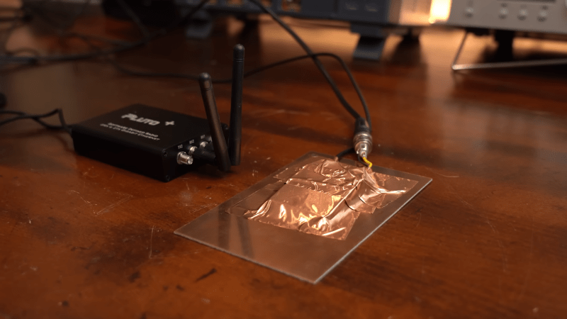
[GreatScott] has recently been tinkering in the world of radio frequency emissions, going so far as to put their own designs in a proper test chamber to determine whether they meet contemporary standards for noise output. This led them to explore the concept of shielding, and how a bit of well-placed metal can make all the difference in this regard.
The video focuses on three common types of shielding—absorber sheets, shielding tapes, and shielding cabinets. A wide variety of electronic devices use one or more of these types of shielding. [GreatScott] shows off their basic effectiveness by putting various types of shielding in between a noise source and a near-field probe hooked up to a receiver. Just placing a bit of conductive material in between the two can cut down on noise significantly. Then, a software defined radio (SDR) was busted out for some more serious analysis. [GreatScott] shows how Faraday cages (or simple shielding cabinets] can be used to crush down spurious RF outputs to almost nothing, and how his noisy buck-boost designs can be quieted down with the use of the right absorber sheets that deal well with the problematic frequencies in question. The ultimate upshot of the tests is that higher frequencies respond best to conductive shielding that is well enclosed, while lower frequency noise benefits from more absorptive shielding materials with the right permeability for the job.
Shielding design can be a complex topic that you probably won’t master in a ten minute YouTube video, but this content is a great primer if you’re new to the topic. We’ve covered the topic before, too, particularly on how a bit of DIY shielding can really aid a cheap SDR’s performance. Video after the break.
 In verband met carnaval is er op 11 en 18 februari geen bijeenkomst in Spaubeek.
Aan alle carnavalsvierders: een fijne carnaval gewenst!
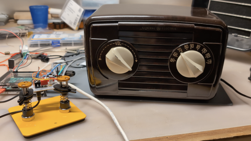
Although we do often see projects that take antiques and replace some or all of their components with modern equipment, we can also sympathize with the view that (when possible and practical) certain antique electronics should be restored rather than gutted. [David] has this inclination for his 1948 GE radio, but there are a few issues with it that prevented a complete, period-correct restoration.
The main (pun intended) issue at the start of this project was safety. The original radio had a chassis that was just as likely as not to become energized, with the only protection being the plastic housing. [David] set up an isolation transformer with a modern polarized power cable to help solve this issue, and then got to work replacing ancient capacitors. With a few other minor issues squared away this is all it took to get the radio working to receive AM radio, and he also was able to make a small modification to allow the radio to accept audio via a 3.5mm jack as well.
However, [David] also has the view that a period-correct AM transmission should accompany this radio as well and set about with the second bit of this project. It’s an adaptation of a project called FieldStation42 originally meant to replicate the experience of cable TV, but [Shane], the project’s creator, helped [David] get it set up for audio as well. A notable feature of this system is that when the user tunes away from one station, it isn’t simply paused, but instead allowed to continue playing as if real time is passing in the simulated radio world.
Although there are a few modern conveniences here for safety and for period-correct immersion, we think this project really hits the nail on the head for preserving everything possible while not rolling the dice with 40s-era safety standards. There’s also a GitHub page with some more info that [David] hopes to add to in the near future. This restoration of a radio only one year newer has a similar feel, and there are also guides for a more broad category of radio restorations as well.
 Tijdens de ALV van dinsdag 20 januari hebben de aanwezige leden unaniem ingestemd met de installatie van een deels nieuw bestuur:
Voorzitter: Thijs Has PE1RLN
Penningmeester: Mark Vroomen PC9DB
Secretaris: Thijs Has PE1RLN a.i.
Het nieuwe bestuur benadrukt dat ze het komende jaar zelf NIETS zullen doen aan huisvesting, bijeenkomsten en activiteiten, dat komt volledig voor rekening van de leden. Het bestuur zal alle initiatieven faciliteren, waar nodig begeleiden en financieren en indien noodzakelijk geacht een bijzondere ledenvergadering bijeenroepen (bijvoorbeeld bij het bepalen van een nieuwe locatie).
Het bestuur is bereikbaar via de mailadressen en natuurlijk op de clubavonden.