Op maandag 4 maart 2024 zijn alle leden van de VRZA afdeling Zuid-Limburg uitgenodigd om deel te nemen aan de Algemene Ledenvergadering. De vergadering start om stipt 20:00 uur in ’t Volkshuis, Dennestraat 2 te Heerlen.
Iedereen die op die datum lid is, is van harte uitgenodigd.
De afdeling ontbeert nog een secretaris, een onmisbare functie die momenteel wordt waargenomen door de voorzitter. Aangezien dit teveel werk is voor een dubbelfunctie, legt de voorzitter de taken van secretaris neer. Als deze functie niet door een nieuwe functionaris wordt ingevuld, zal er geen jaarverslag kunnen worden gemaakt, is er geen vertegenwoordiging in de Stichting Radioamateurstations Zuid-Limburg (de repeater stichting) en loopt de vereniging de jaarlijkse bijdrage mis! Deze financiële middelen en inspraak zijn onmisbaar dus stelt u zich verkiesbaar!
De voorlopig agenda is als volgt. Indien u agendapunten wenst in te dienen, dan kan dat tot en met zondag 3 maart.
AGENDA
- Opening door de voorzitter
- Vaststellen van de agenda
- Vaststellen notulen ALV 2023
- Verslag van de voorzitter
- Verslag van de penningmeester
- Verslag van de kascontrolecommissie
- Kiezen vacante functie van secretaris
- Activiteiten 2024
- Velddag (Roberto)
- Repeater (Thijs)
- Radiomarkt (Roberto)
- Rooster van aftreden (3-jaarlijks) goedkeuren door de leden
- Voorzitter: Thijs PE1RLN treedt af tijdens ALV 2025
- John van Venrooij PE1SBN treedt af tijdens ALV 2027
- Roberto Duckers PD0DX treedt af tijdens ALV 2027
- Rondvraag
- Sluiting door de voorzitter
Indien u zich verkiesbaar wilt stellen voor de functie van secretaris en/of agendapunten wilt inbrengen dan kan dat tot en met zondag 3 maart 2024 per e-mail: thijs@gerlachus.com . Tijdens de vergadering is dit niet meer mogelijk.
U hoeft zich voor de vergadering niet aan of af te melden. Voorafgaand aan de vergadering dient u wel de presentielijst aldaar te tekenen.
Tot maandag 4 maart 2024!
Verslag van de Algemene Ledenvergadering 2023 van afdeling 23 van de VRZA.
Gehouden op maandag 3 maart 2023 in het Volkshuis, gelegen aan de Dennenstraat 2 te Heerlen/Passart.
Aanwezig zijn 12 leden en 4 bestuursleden.
Afmelding ontvangen van: PE1OJX, PA0EJM, PA3HH, PD0RTL, PA3CK.
Aanwezig: PA0EJH, PA3CBH. PD1NL, PE1DVN, PE1IIG, PE1LHC, PA3HFH, PA3PCV, PA4GR, PE1MFS, PE1RIU, PE1SBN.
1.:Opening: De voorzitter: Thijs-PE1RLN opent de vergadering en heet iedereen welkom.
2.: Notulen: Er zijn geen vragen en opmerkingen over het vorig verslag (2022).
3.: Terugblik en vooruitblik: Zie verhaal Thijs (voorzitter)
4.: Ingekomen: enkele bladen van andere afdelingen, verslag van de medewerkersdag, uitnodiging voor de Algemene Ledenvergadering, de concept notulen van de ALV van 2022 en de aan en afmeldingen van diverse leden en een mail/bericht voor deelname aan de WAP in november.
De voorzitter spreekt weer zijn dank uit aan Egbert-PA0EJH voor het afhandelen van diverse technische vragen.
Door de QSL manager wordt medegedeeld dat de niet afgehaalde QSL kaarten na 1 jaar teruggestuurd worden.
5.: Financiën:
a: Er zijn geen vragen over het financieel jaarverslag 2022.
b: Idem over de jaaropgave.
c: begroting 2023:
6.: De kascontrolecommissie:
De kascommissie, bestaande uit: Egbert-PA0EJH en Cor-PA3CK. Zij hebben de boeken van 2022 gecontroleerd.
Alles zag er overzichtelijk uit en was goed controleerbaar.
De commissie stelt de vergadering voor het bestuur decharge voor het jaar 2022 te verlenen.
De vergadering stemt hiermee in.
Voor het boekjaar 2023 zullen de stukken worden gecontroleerd door: Jos-PE1RII en Guido-PA4GR. . Reserve lid: Winand-PE1DVN.
7.: Verkiezingen:
Er heeft 1 kandidaat zich beschikbaar gesteld voor de functie penningmester.
Thijs bedankt Paul en Rudolf voor hun inzet in het bestuur.
Hij deelt mede dat Hij zich 3 jaar wil inzetten als voorzitter van de afdeling.
Roberto neemt als lid van het bestuur het promoten van de activiteiten op zich.
John- PE1SBN stelt zich beschikbaar als penningmeester.
De 3 voorstellen worden door de leden aangenomen.
8.: Actiepunten 2023:
– Thijs noemt 3 speerpunten op: Repeater, Velddag en radiomarkt.
De voorzitter zal een vergadering van de Stichtring bijeenroepen om de toekomst van de repeater te bespreken.
- De Velddag:commissie maakt een voorstel voor 2023.
- : de markt zal in 2023 gehouden worden onder de naam: VRZA en Veron. De Veron heeft een verzekering voor dergelijke activiteiten. Winand vraagt naar de kosten van de tafels en dekzeilen. Het bestuur weet het niet. Wel is er voldoende in de kas om deze kosten te dekken indien er te weinig tafels besteld worden. John-SBN merkt op dat er veel oude troep is en het aanbod is slecht.
- Thijs stelt dat er mogelijk in het Volkshuis een markt gehouden kan worden. Het bestuur zal dat nagaan.
De lezingen : het wordt steeds moeilijker om onderwerpen en spreker te vinden. Thijs stelt voor om met de Veron te bespreken of en minder lezingen gehouden kunnen worden, bijv. niet in de zomer.
Ook is een mogelijkheid om door de Veron 4 lezingen te houden en 4 door de VRZA.
9.: Rondvraag:
Er wordt geen gebruik gemaakt van de rondvraag.
9.: Sluiting: De voorzitter sluit de bijeenkomst en nodigt de aanwezigen uit voor een gratis drankje.
Notulist: Rudolf, pa1ebm, ex-secretaris afdeling 23.
 In verband met kerstmis zal er op maandag 25 december GEEN bijeenkomst zijn, evenals op maandag 1 januari.
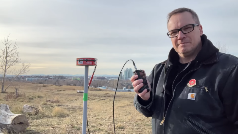
 Aan de Hulsbergse repeater is een extra ontvanger toegevoegd in… Hulsberg! Enkele honderden meters verderop is de invloed van de zonnepanelen afwezig en kan een extra ontvanger ervoor zorgen dat er ook bij zonnig weer gebruik kan worden gemaakt.
 Vind je het leuk en interessant om op zondag naar de ronde te luisteren? Misschien vind je het ook wel leuk om ‘m zelf eens te leiden? Dat kan!