De laatste tijd is er iemand actief op de repeater (en wellicht ook op andere frequenties) die misbruik maakt van de roepletters PD1JOL. Dit is uiteraard niet de bedoeling en daarom het verzoek om de betreffende persoon aan te spreken op het illegale gebruik van andersmans roepletters. Daarna moet het QSO worden beëindigd want het is niet toegestaan een QSO te voeren met iemand die niet over een vergunning beschikt.
Kunstroute & radiozendamateurs

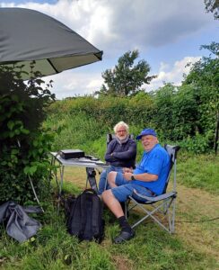
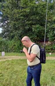
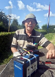
Op zondag 25 augustus werd rond de Van Tienhovenmolen in Wolfshuis bij Bemelen een kunstroute georganiseerd: allerlei kunstenaars exposeerden hun kunst in de buurt en bij de molen. Zoals altijd bij zulke activiteiten, maakt een groep zendamateurs ook hun opwachting, in dit geval met kunstige antennes en verbindingen.
Prachtig weer, een misschien nog wel prachtigere omgeving en leuke verbindingen met oa Brazilië maar ook met de aanwezigen die het over het algemeen zeer interessant vonden en verbaasd waren dat je met het vermogen van 100W met de andere kant van de wereld kunt praten via een vishengel. Fascinerend.
Hidden Gutter Antenna Keeps HOA Happy
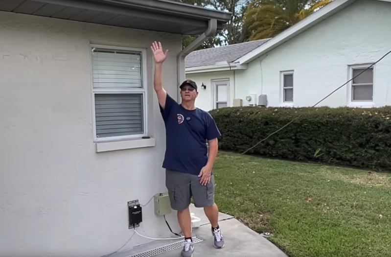
The United States and a few other countries have an astounding array of homeowners’ associations (HOAs), local organizations that exert an inordinate influence on what homeowners can and can’t do with their properties, with enforcement mechanisms up to foreclosure. In the worst cases they can get fussy about things like the shade of brown a homeowner can paint their mailbox post, so you can imagine the problems they’d have with things like ham radio antennas. [Bob] aka [KD4BMG] has been working on tuning up his rain gutters to use as “stealth” antennas to avoid any conflicts with his HOA.
With the right antenna tuner, essentially any piece of metal can be connected to a radio and used as an antenna. There are a few things that improve that antenna’s performance, though. [Bob] already has an inconspicuous coax connector mounted on the outside of his house with an antenna tuner that normally runs his end-fed sloper antenna, which also looks like it includes a fairly robust ground wire running around his home. All of this is coincidentally located right beside a metal downspout, so all this took to start making contacts was to run a short wire from the tuner to the gutter system.
With the tuner doing a bit of work, [Bob] was able to make plenty of contacts from 10 to 80 meters, with most of the contacts in the 20 – 30 meter bands. Although the FCC in the US technically forbids HOAs from restricting reasonable antennas, if you’d rather not get on the bad side of your least favorite neighbors there are a few other projects from [Bob] to hide your gear.
An Antenna To Throw You For A Loop
It is one of Murphy’s laws, we think, that you can’t get great things when you need them. Back in the heyday of shortwave broadcasting, any of us would have given a week’s pay for even a low-end receiver today. Digital display? Memory? Digital filtering? These days, you have radios, and they aren’t terribly expensive, but there isn’t much to listen to. Making matters worse, it isn’t easy these days to string wires around in your neighborhood for a variety of reasons. Maybe you don’t have a yard, or you have deed restrictions, or your yard lacks suitable space or locations. This problem is so common that there are a crop of indoor antennas that seem attractive. Since I don’t often tune in shortwave and I don’t want to have to reset my antenna after every storm, I decided to look at the Tecsun AN-48X along with a YouLoop clone from China. Let’s start with the Tecsun.
In the Box
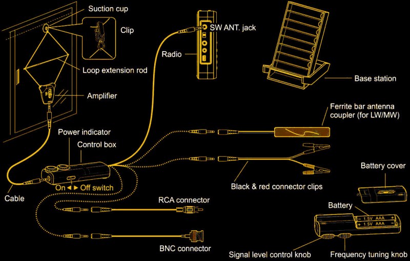
The antenna is not terribly cheap at about $50 or so, but there’s a lot in the box. The business end looks like something you’d wear around your neck. A small box has a switch for three bands — LW, AM, and SW. the two wires coming out of that box form a loop. You can stick the loop to something using a suction cup or a hook. There’s also a little bar that looks like a standard telescoping antenna but it has two plastic clips on the end. You use this to form the loop into a diamond shape with the telescoping rod about halfway.
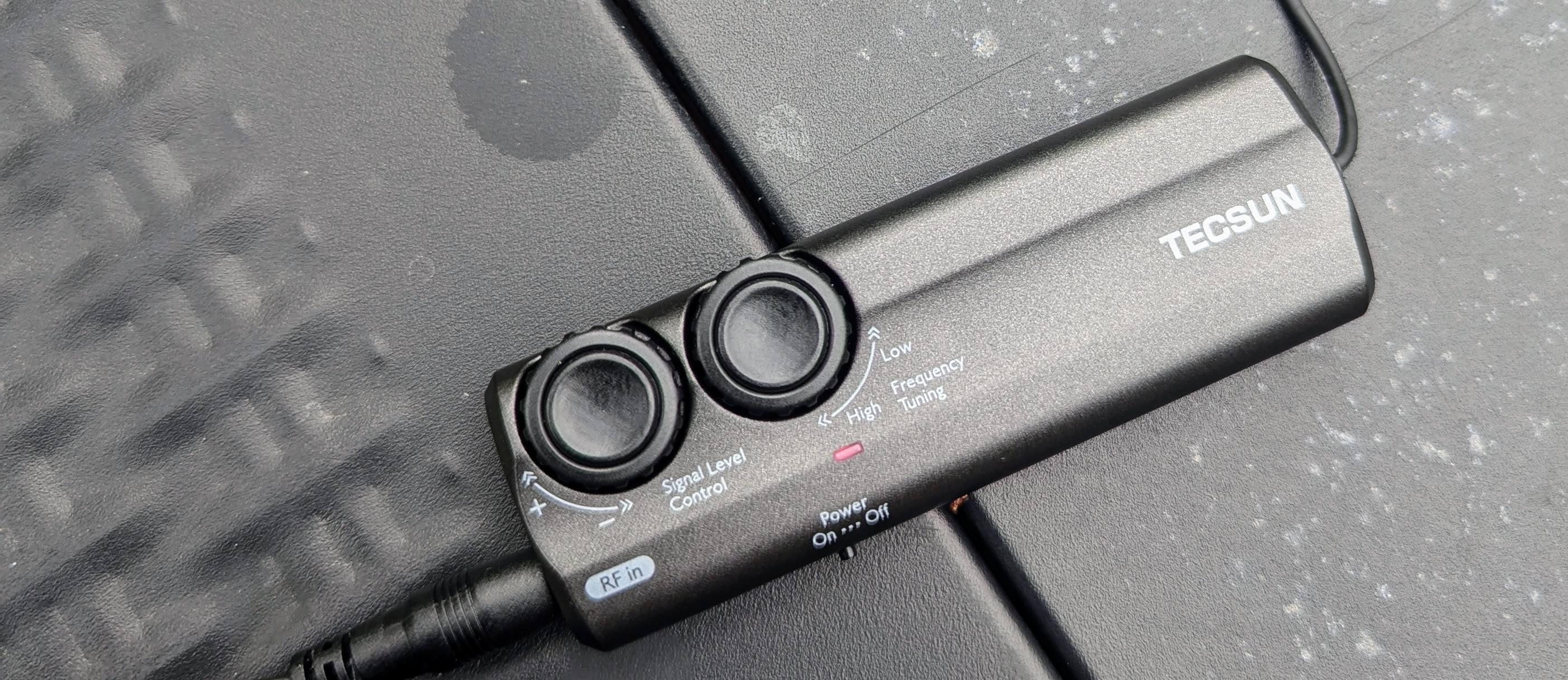
At the bottom of the box with the switch is a standard 1/8″ jack. A cable connects that jack to a similar jack on the control unit which is about the size of a large pack of gum and has two AAA batteries inside. That box has a switch, two knobs, and a pigtail with another 1/8″ jack.
If your radio takes a 1/8″ plug for an antenna, that’s where you connect it. If it doesn’t, you have a few options. The box contains pigtails that convert the plug to BNC, RCA, alligator clips, or a ferrite bar that can couple to a radio’s internal antenna. You probably need SMA for a modern radio, so you’ll need an adapter. There’s also a plastic stand that can hold your radio and the ferrite bar if you are using it.
The knobs on the control box control the gain and tune the frequency of the antenna. Other than the switch close to the loop, all the other controls are on the control box, which stays close to your radio. So, as long as you don’t care about jumping between LW, AM, and SW, you don’t need to access the loop part during operation.
A Few Tests
I decided to try the antenna at a few different times a day in a few different locations. I used an old portable DAK shortwave receiver and also a more modern SDR receiver.
For the first test, I hung the loop on my upstairs stair rail and let the cable drop down to the first floor. During the day, WWV was barely audible, and there was little else to hear outside of noise. Granted, this was indoors. The signal level control didn’t seem to do much. The tuning frequency knob reminded me of a regenerative receiver control. You could hear the device oscillate, and just past the oscillation, you’d get the best signal. It made me wonder if the inner circuit was, in fact, a regenerative amplifier.
The portable shortwave uses a regular jack, but for the Malachite, I had to use a BNC to SMA adapter. Neither radio could pull much out. Nighttime reception was a little better, but not much.
The Great Outdoors
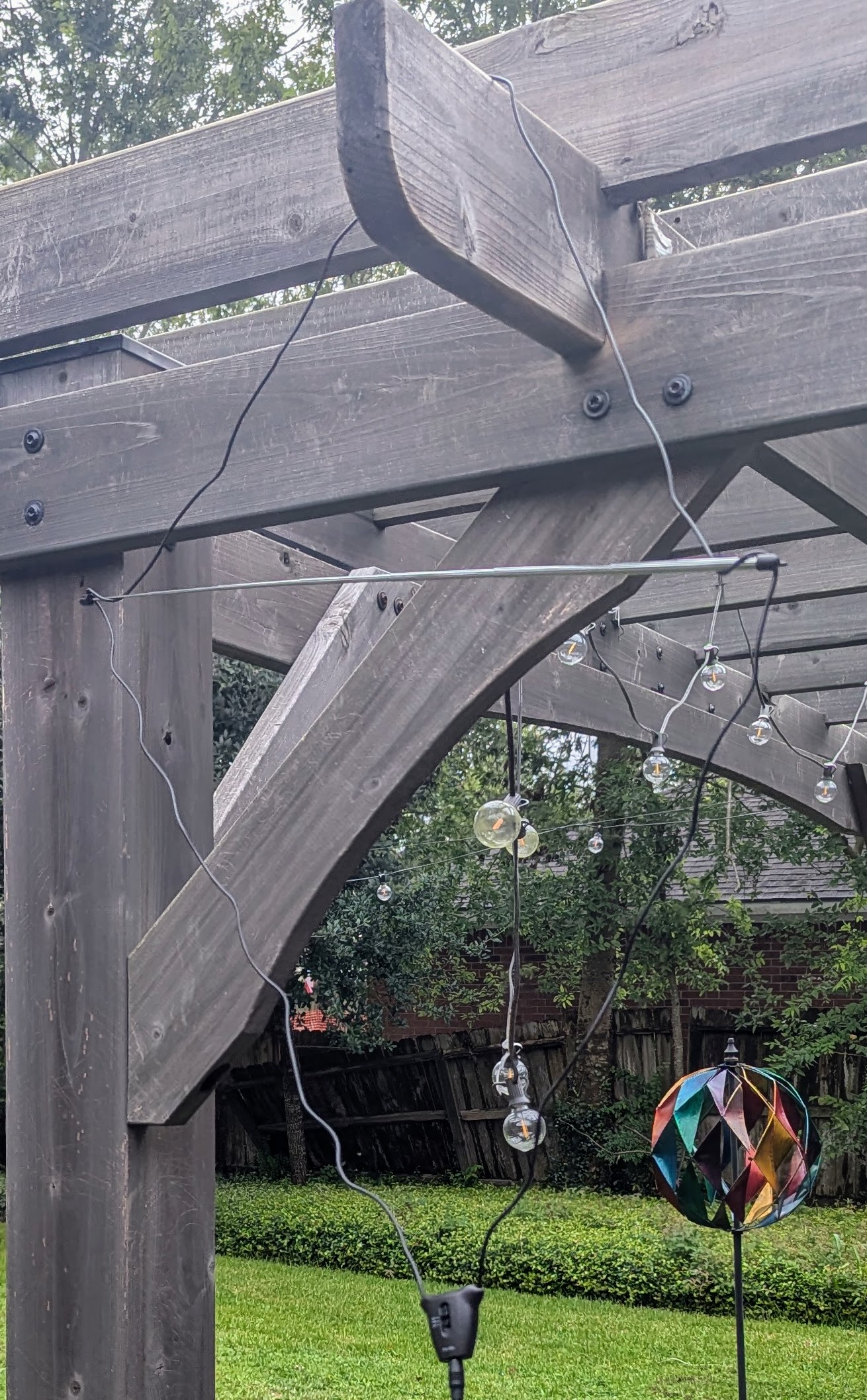
Unsurprisingly, the device worked a little better outdoors. I hung it from an exposed beam on a pergola, and at night, there were a few fairly clear signals. During the daylight hours, WWV was elusive, but the Voice of America and Radio Havana — not too far from Houston — were easy to copy, especially if you understand French. I even managed to catch a few faint snags of WWVH.
The video below shows a few audio clips of the results. Forgive the outdoor glare on the screen in the first clip. I omitted the clips with music that YouTube might flag, but you get the idea.
I also tested a YouLoop clone. This worked almost as well as the Techsun, but not quite as well. However, there was nothing to fidget with on the frequency.
The YouLoop
The YouLoop has an interesting idea. It uses coax for the loop and configures it like a Mobius strip so that it is kind of, an infinite loop. At the bottom is a balun with three connectors, and at the top is a phase inverter. That sounds fancy, but it really is just a box that connects the inside of one cable to the outside of the other. The antenna came with a powered preamp, although if your radio has a preamp, you probably don’t need it.
It is handy that it just works, and the coax sections are stiff enough to be easy to handle when you want to hang it from a branch, for example. However, it also doesn’t pack down as tightly, and the boxes are metal, which adds to the weight but is probably better for shielding.
Signals on this loop were almost always lower in volume than the same signal from the Tecsun, even with the preamp. On the other hand, if you don’t need the preamp, this antenna takes no batteries. It is simple enough that you can try it and see if you like it without a major investment.
Observations
While the Tecsun is light, I can’t help but wonder if the shielded feedline might not have helped it. For both antennas, having the preamp close up to the feed point might pay off, although maybe some of the wire between the antenna and the control boxes or preamp becomes part of the antenna. It isn’t, after all, a tuned antenna.
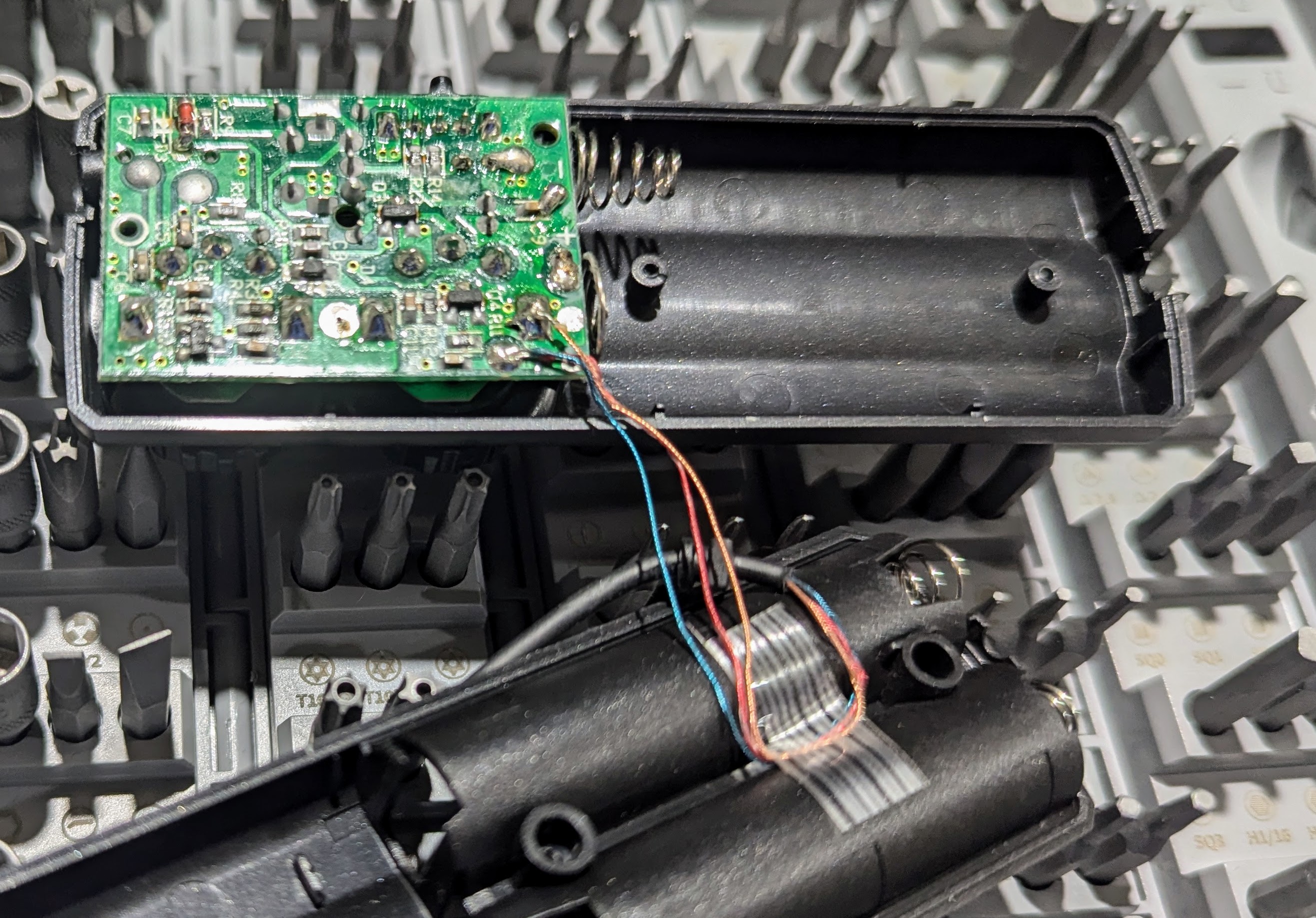
The Tecsun’s control box frequency knob is maddeningly sensitive, but it does seem to help things. Inside the box is a tiny PCB, and I didn’t find any online schematics.
Should you run out and get either of these antennas? If you have other options, probably not. But if you need something, both of them are better than nothing.
If you haven’t had a shortwave radio in a while, they are surprisingly cheap these days. Well, most of them, anyway.
Is Shortwave On Life Support?
Between World War II and Y2K, shortwave listening was quite an education. With a simple receiver, you could listen to the world. Some of it, of course, was entertainment, and much of it was propaganda of one sort or another. But you could learn a lot. Kids with shortwave radios always did great in geography. Getting the news from a different perspective is often illuminating, too. Learning about other cultures and people in such a direct way is priceless. Getting a QSL card in the mail from a faraway land seemed very exciting back then.
Today, the shortwave landscape is a mere shadow of itself. According to a Wikipedia page, there are 235 active shortwave broadcasters from a list of 414, so nearly half are defunct. Not only are there many “dead” shortwave outlets, but many of the ones that are left are either not aimed at the world market or serve a niche group of listeners.
You can argue that with the Internet, you don’t need radio, and that’s probably correct in some ways but misses a few important points. Indeed, many broadcasters still exist as streaming stations or a mix of radio and streaming. I have to admit I listen to the BBC often but rarely on the air. My computer or phone plays it in crystal clarity 24 hours a day.

So, while a 14-year-old in 1975 might be hunched over a radio wearing headphones, straining to hear NHK World Radio, these days, they are likely surfing the popular social media site of the week. You could easily argue that content on YouTube, Instagram, and the like can come from all over the world, so what’s the problem?
The problem is information overload. Faced with a shortwave radio, there were a limited number of options available. What’s more, only a small part of the band might be “open” at any given time. It isn’t like the radio could play games or — unless you were a ham — allow you to chat with your friends. So you found radio stations from Germany to South Africa. From China and Russia, to Canada and Mexico. You knew the capital of Albania. You learned a little Dutch from Radio Nederlands.
Is there an answer? Probably not. Radio isn’t coming back, barring an apocalyptic event. Sure, you can listen to the BBC on your computer, but you probably won’t. You can even listen to a radio over the network, but that isn’t going to draw in people who aren’t already interested in radio, even if it really looks like a radio.
If you made a website with radio stations of the world, would people use it? Something like a software version of this globe or a “world service” version of RadioGarden. Probably not.
Do you listen to shortwave radio? If so, what are you listening to? Do you listen to “world services” at all? Tell us in the comments. Many careers were launched by finding a shortwave radio under the Christmas tree at just the right age. When Internet access is compromised, there’s still no substitute for real radios. If you want to listen to some of those vintage programs, they are — unsurprisingly — on the Internet.
Tiny Transceiver Gets It Done With One Transistor
When we first spotted the article about a one-transistor amateur radio transceiver, we were sure it was a misprint. We’ve seen a lot of simple low-power receivers using a single transistor, and a fair number of one-transistor transmitters. But both in one package with only a single active component? Curiosity piqued.
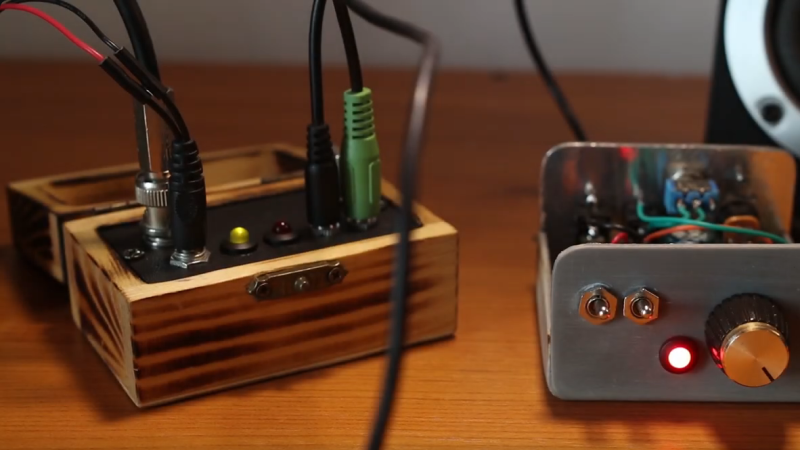
It turns out that [Ciprian Popica (YO6DXE)]’s design is exactly what it says on the label, and it’s pretty cool to boot. The design is an improvement on a one-transistor transceiver called “El Pititico” and is very petite indeed. The BOM has only about fifteen parts including a 2N2222 used as a crystal-controlled oscillator for both the transmitter and the direct-conversion receiver, along with a handful of passives and a coupe of hand-wound toroidal inductors. There’s no on-board audio section, so you’ll have to provide an external amplifier to hear the signals; some might say this is cheating a bit from the “one transistor” thing, but we’ll allow it. Oh, and there’s a catch — you have to learn Morse code, since this is a CW-only transmitter.
As for construction, [Ciprian] provides a nice PCB layout, but the video below seems to show a more traditional “ugly style” build, which we always appreciate. The board lives in a wooden box small enough to get lost in a pocket. The transceiver draws about 1.5 mA while receiving and puts out a fairly powerful 500 mW signal, which is fairly high in the QRP world. [Ciprian] reports having milked a full watt out of it with some modifications, but that kind of pushes the transistor into Magic Smoke territory. The signal is a bit chirpy, too, but not too bad.
We love minimalist builds like these; they always have us sizing up our junk bin and wishing we were better stocked on crystals and toroids. It might be good to actually buckle down and learn Morse too.
RX-4 voor PI3ZLB klaar voor gebruik
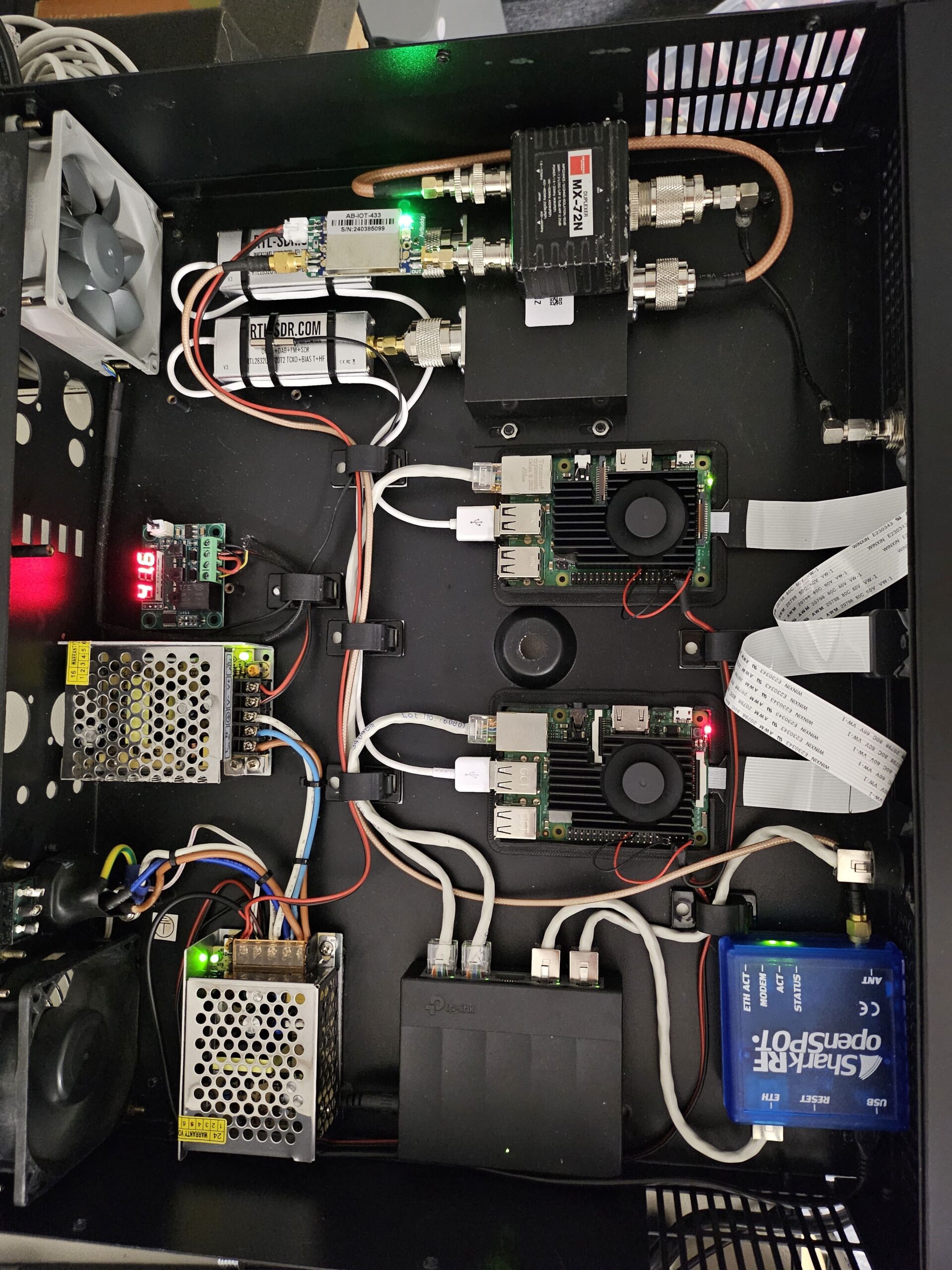
Sinds enige tijd draaien er 3 extra ontvangers mee in het netwerk van de repeater om zo het ontvangstbereik te maximaliseren. In Hulsberg bevindt zich niet alleen de repeater zelf maar enkele honderden meters verderop ook de 4e ontvanger. Deze is gedoneerd door Thijs, PE1RLN die de ontvanger zelf samenstelde en samen met Folkert heeft getest en afgeregeld.
De ontvanger bestaat uit een Raspberry Pi en een RTL-SDR stick, meer niet. De gevoeligheid was in het begin zelfs wat te groot maar na wat afregelen en 3dB demping werkt het als een zonnetje. Die 3dB demping komt door een passieve splitter die de antenne laat delen met de APRS iGate die over dezelfde hardware beschikt die alle ontvangen APRS stations deelt met de APRS.fi server. En toen Thijs toch bezig was, installeerde hij nog een D-Star hotspot in dezelfde behuizing die middels een diplexer op 70cm dezelfde antenne nogmaals gebruikt. Door toepassing van een kleine powemodule wordt het uitgangsvermogen 200mW wat voor heel Hulsberg zorgt voor zorgeloos gebruik tijdens wandelingen.
Het geheel is netjes ingebouwd in een 19″ rackbehuizing zodat het niet alleen netjes oogt maar ook stevig en betrouwbaar is ingebouwd.
VHF/UHF Antennas, The Bad, The Ugly, And The Even Worse
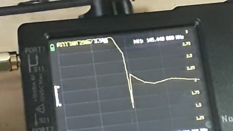
When you buy a cheap ham radio handy-talkie, you usually get a little “rubber ducky” antenna with it. You can also buy many replacement ones that are at least longer. But how good are they? [Learnelectronics] wanted to know, too, so he broke out his NanoVNA and found out that they were all bad, although some were worse than others. You can see the results in the — sometimes fuzzy — video below.
Of course, bad is in the eye of the beholder and you probably suspected that most of them weren’t super great, but they do seem especially bad. So much so, that, at first, he suspected he was doing something wrong. The SWR was high all across the bands the antennas targeted.
It won’t come as a surprise to find that making an antenna work at 2 meters and 70 centimeters probably isn’t that easy. In addition, it is hard to imagine the little stubby antenna the size of your thumb could work well no matter what. Still, you’d think at least the longer antennas would be a little better.
Hams have had SWR meters for years, of course. But it sure is handy to be able to connect an antenna and see its performance over a wide band of frequencies. Some of the antennas weren’t bad on the UHF band. That makes sense because the antenna is physically larger but at VHF the size didn’t seem a big difference.
He even showed up a little real-world testing and, as you might predict, the test results did not lie. However, only the smallest antenna was totally unable to hit the local repeater.
Of course, you can always make your own antenna. It doesn’t have to take much.
Cavity Filters, The Black Art You Have A Chance Of Pursuing
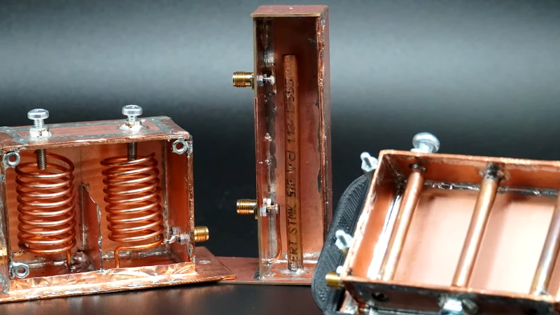
A tuned circuit formed by a capacitor and an inductor is a familiar enough circuit, and it’s understood that it will resonate at a particular frequency. As that frequency increases, so the size of the capacitor and inductor decrease, and there comes a point at which they can become the characteristic capacitance and inductance of a transmission line. These tuned circuits can be placed in an enclosure, at which they can be designed for an extremely high Q factor, a measure of quality, and thus a very narrow resonant point. They are frequently used as filters for that reason, and [Fesz] is here with a video explaining some of their operation and configurations.
Some of the mathematics behind RF design can be enough to faze any engineer, but he manages to steer a path away from that rabbit hole and explain cavity filters in a way that’s very accessible. We learn how to look at tuned circuits as transmission lines, and the properties of the various different coupling methods. Above all it reveals that making tuned cavities is within reach.
They’re a little rare these days, but there was a time when almost every TV set contained a set of these cavities which were ready-made for experimentation.
Hacking A Quansheng Handheld To Transmit Digital Modes
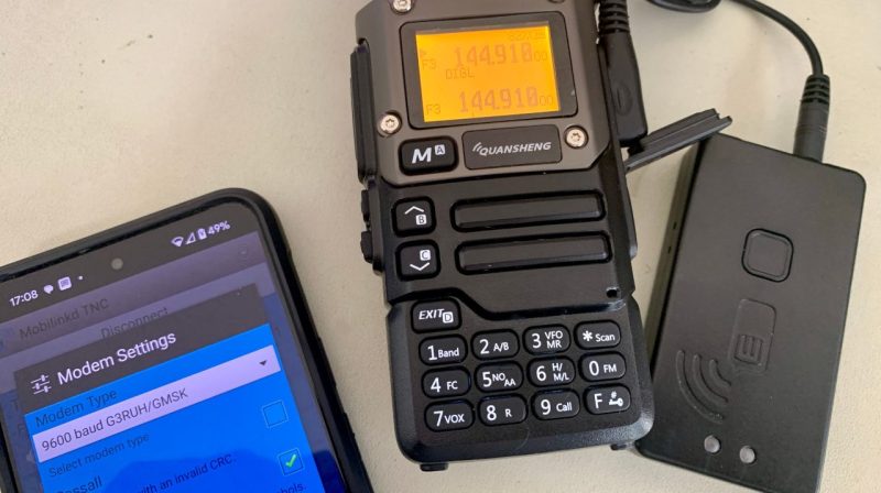
Have you ever thought about getting into digital modes on the ham bands? As it turns out, you can get involved using the affordable and popular Quansheng UV-K6 — if you’re game to modify it, that is. It’s perfectly achievable using the custom Mobilinkd firmware, the brainchild of one [Rob Riggs].
In order to efficiently transmit digital modes, it’s necessary to make some hardware changes as well. Low frequencies must be allowed to pass in through the MIC input, and to pass out through the audio output. These are normally filtered out for efficient transmission of speech, but these filters mess up digital transmissions something fierce. This is achieved by messing about with some capacitors and bodge wires. Then, one can flash the firmware using a programming cable.
With the mods achieved, the UV-K6 can be used for transmitting in various digital modes, like M17 4-FSK. The firmware has several benefits, not least of which is cutting turnaround time. This is the time the radio takes to switch between transmitting and receiving, and slashing it is a big boost for achieving efficient digital communication. While the stock firmware has an excruciating slow turnaround of 378 ms, the Mobilinkd firmware takes just 79 ms.
Further gains may be possible in future, too. Bypassing the audio amplifier could be particularly fruitful, as it’s largely in the way of the digital signal stream.
Quansheng’s radios are popular targets for modification, and are well documented at this point.