Op zondag 17 november vindt van 13:00 tot 16:00 uur de QSO party plaats: afdelingen van de VRZA zijn dan op 2m, 40m (NIEUW) en 80m QRV om verbindingen te maken.
Uiteraard is Zuid-Limburg ook van de partij! Vanuit een locatie in het Heuvelland zal een kleine groep amateurs de zenders bemannen. Gezien de piepkleine locatie, is de groep actieve deelnemers beperkt.
As far as hobbies go, ham radio tends to be on the more expensive side. A dual-band mobile radio can easily run $600, and a high-end HF base station with the capability of more than 100 watts will easily be in the thousands of dollars. But, like most things, there’s an aspect to the hobby that can be incredibly inexpensive and accessible to newcomers. Crystal radios, for example, can be built largely from stuff most of us would have in our parts drawers, CW QRP radios don’t need much more than that, and sometimes even the highest-performing antennas are little more than two lengths of wire.
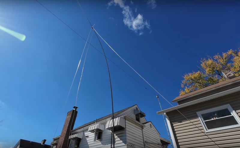
For this specific antenna, [W3CT] is putting together an inverted-V which is a type of dipole antenna. Rather than each of the dipole’s legs being straight, the center is suspended at some point relatively high above ground with the two ends closer to the earth. Dipoles, including inverted-Vs, are resonant antennas, meaning that they don’t need any tuning between them and the radio so the only thing needed to match the antenna to the feed line is a coax-to-banana adapter. From there it’s as simple as attaching the two measured lengths of wire for the target band and hoisting the center of the antenna up somehow. In [W3CT]’s case he’s using a mast which would break the $8 budget, but a tree or building will do just as well.
The video on the construction of this antenna goes into great detail, so if you haven’t built a dipole yet or you’re just getting started on your ham radio journey, it’s a great place to get started. From there we’d recommend checking out an off-center-fed dipole which lets a dipole operate efficiently on multiple bands instead of just one, and for more general ham radio advice without breaking the bank we’d always recommend the $50 Ham series.
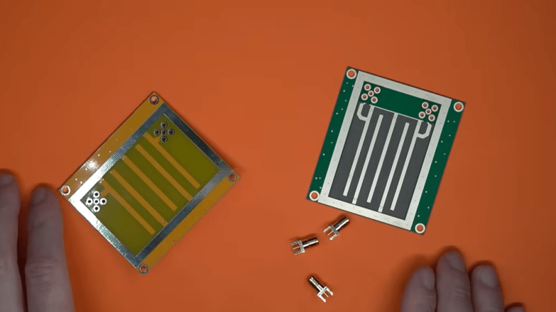
We’ve always been fascinated by things that perform complex electronic functions merely by virtue of their shapes. Waveguides come to mind, but so do active elements like filters made from nothing but PCB traces, which is the subject of this interesting video by [FesZ].
Of course, it’s not quite that simple. A PCB is more than just copper, of course, and the properties of the substrate have to be taken into account when designing these elements. To demonstrate this, [FesZ] used an online tool to design a bandpass filter for ADSB signals. He designed two filters, one using standard FR4 substrate and the other using the more exotic PTFE.
He put both filters to the test, first on the spectrum analyzer. The center frequencies were a bit off, but he took care of that by shortening the traces slightly with a knife. The thing that really stood out to us was the difference in insertion loss between the two substrates, with the PTFE being much less lossy. The PTFE filter was also much more selective, with a tighter pass band than the FR4. PTFE was also much more thermostable than FR4, which had a larger shift in center frequency and increased loss after heating than the PTFE. [FesZ] also did a more real-world test and found that both filters did a good job damping down RF signals across the spectrum, even the tricky and pervasive FM broadcast signals that bedevil ADSB experimenters.
Although we would have liked a better explanation of design details such as via stitching and trace finish selection, we always enjoy these lessons by [FesZ]. He has a knack for explaining abstract concepts through concrete examples; anyone who can make coax stubs and cavity filters understandable has our seal of approval.
Even if you are relatively young, you can probably think back on what TV was like when you were a kid and then realize that TV today is completely different. Most people watch on-demand. Saturday morning cartoons are gone, and high-definition digital signals are the norm. Many of those changes are a direct result of the Internet, which, of course, changed just about everything. Ham radio is no different. The ham radio of today has only a hazy resemblance to the ham radio of the past. I should know. I’ve been a ham for 47 years.
You know the meme about “what people think I do?” You could easily do that for ham radio operators. (Oh wait, of course, someone has done it.) The perception that hams are using antique equipment and talking about their health problems all day is a stereotype. There are many hams, and while some of them use old gear and some of them might be a little obsessed with their doctor visits, that’s true for any group. It turns out there is no “typical” ham, but modern tech, globalization, and the Internet have all changed the hobby no matter what part of it you enjoy.
Radios
One of the biggest changes in the hobby has been in the radio end. Hams tend to use two kinds of gear: HF and VHF/UHF (that’s high frequency, very high frequency, and ultra-high frequency). HF gear is made to talk over long distances, while VHF/UHF gear is for talking around town. It used to be that a new radio was a luxury that many hams couldn’t afford. You made do with surplus gear or used equipment.
Globalization has made radios much less expensive, while technological advances have made them vastly more capable. It wasn’t long ago that a handy-talkie (what normal folks would call a walkie-talkie) would be a large purchase and not have many features. Import radios are now sophisticated, often using SDR technology, and so cheap that they are practically disposable. They are so cheap now that many hams have multiples that they issue to other hams during public service events.
Because these cheap ($20-$40) radios often use SDR, they can even be hacked. These radios aren’t typically the highest quality if you are used to repurposed commercial gear, but when you can replace the radio for $20, it hardly matters.
HF radios are a different story. Thanks to software-defined radio, superpowerful computers, and FPGAs, even relatively inexpensive HF radios have features that would have seemed like magic when I first got my license.
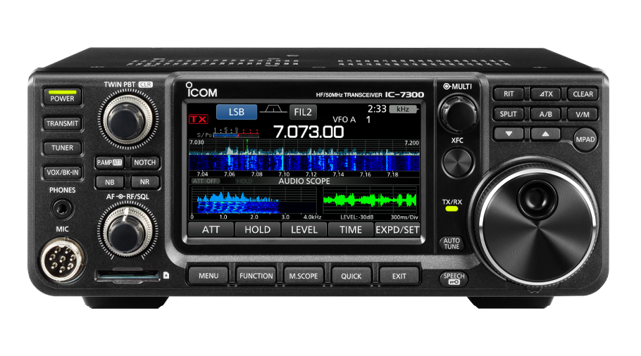
The ICOM IC-7300 is considered a “starter” radio!
While some hams like to build gear or use simple or older gear, modern transceivers, like the IC-7300 from Icom shown here, have incredible RF filtering done in software, spectrum analyzers, and scopes built in. The 7300, by the way, isn’t considered a “top of the line” radio by any means. But it has features that would have been a dream on a state of the art unit before the advent of DSP.
Having these kind of tools changes how you operate. In the old days, you’d tune around to see if you could hear anyone. Now, glancing at the screen will show you all the signals on a band and how strong they are. Touch one, and you tune it in immediately. Digital noise reduction is very helpful these days with so much interference, and, of course, you can control the whole thing from a PC if you want to.
The receivers are exceptional compared to what even a high-end radio would offer a few decades ago. Specialized filters used to be expensive and limited in options. Now, you can design any filter you want on the fly and it will be nearly perfect.
Granted, these radios aren’t in the impulse buy category like the handheld radios. Still, you can find them new for around $1,000 and used for less. There are also other similar radios for much less. Just as you can buy imported handheld VHF and UHF radios, there are imported HF radios that put out a lower wattage (20 watts vs 100 watts is typical). These still have plenty of features, and you can get them for about half the cost of the name-brand 100W rigs. [K4OGO] has a video (see below) about several popular radios in that price range and you’ll notice that many of them have similar displays.
Digital Modes
Paradoxically, you might not need as hot a receiver, or as big of an antenna, or as much power as you might think. Hams have long known that voice communication is inefficient. Morse code could be the earliest form of digital radio communication, allowing a proficient operator to copy signals that would never make a voice contact. However, hams have also long used other digital modes, including TeleType, which is more convenient but less reliable than a good Morse code operator.
That changed with computer soundcards. Your computer can pull signals out of a hash that you would swear was nothing but noise. Modern protocols incorporate error detection and correction, retries, and sophisticated digital signal processing techniques to pull information from what appears to be nowhere.
What kind of sound card do you need? Almost any modern card will do it, but if you have the Icom IC-7300 pictured above, you don’t need one. It turns out, it is a sound card itself. When you plug it into a PC, it offers audio in and out for ham radio programs. It can even send IQ signals directly to the PC for common SDR programs to work with.
Some digital modes are conversational. You can use them like you might a radio-based chat room to talk to people you know or people you’ve just met. However, some modes are more specialized and optimized to make and confirm contact.
Computer Logging
There was a time when every ham had a log book — a notebook to write down contacts — and a stack of QSL cards. Operators would exchange cards in the mail to confirm contact with each other. Many of the cards were interesting, and collecting enough cards could earn an award (for example, working all 50 US states or over 100 foreign countries).
Things are different now. Many people use a computer to track their contacts. While you could just use a spreadsheet, there are many ways to log and — more importantly — share logs online.
The advantage is that when you make a contact and enter into the system, it can match your entry up with your partner’s entry and immediately confirm the contact. This isn’t perfect, because there are several systems people use, but it is possible to interoperate between them. No more waiting for the mail.
DX and Propagation
I mentioned that having a display of the entire ham band changes how you operate. But there is even more help out there. Many people enjoy working rare foreign stations or special event stations held at parks or historical locations. These days, if you hear a station like that on the air, you can report it on the Internet so other people can find them. In some cases, the operator will report themselves, even.
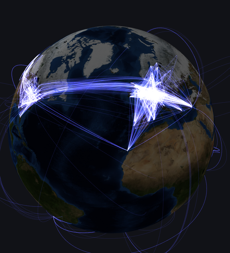
A real-time view of beacon reception across the globe.
Suppose you want to make contact with someone in Kenya because you haven’t done it, and you are working towards an award that counts how many countries you’ve contacted. Instead of searching endlessly, you can simply watch the Internet for when a station from that country appears. Then turn on your radio, use the digital tuning to go exactly to their frequency, and try your luck.
Of course, radio propagation isn’t foolproof. But you can use beacons to determine how propagation is near you. There are many tools to manipulate the beacon data to better understand radio conditions. In fact, if you use digital modes or Morse code, you can find out who’s hearing you on the Internet, which can be very useful.
Why Not You?
Some old hams say the Internet is ruining ham radio. I say it is changing ham radio just like it has changed virtually everything else. Some of those changes aren’t that drastic anyway. For years, people chasing awards, trying to work long distances, or participating in contests have very short contacts. You typically would exchange your name, location, and how strong your signal is and then make way for the next person to make contact. The digital mode FT8 automates all that. It is true that it isn’t very personal, but those kinds of contacts were never personal to start with.
What’s more is that you don’t have to use any of this if you don’t want to. I operate a lot of Morse code with no mechanical assistance. If I hear a big pileup, I might go look at the computer to see who has been spotted on that frequency. But I don’t have to. I could figure it out the old-fashioned way.
Hams work with advanced signal processing software, satellites, moon bounce, support communities, design antennas, foster school education, work during disasters, and push the envelope on microwave communication. No matter what your interests, there’s something you’ll enjoy doing. For many years now, you don’t even have to pass a test for Morse code, so if you didn’t want to learn the code, you don’t have to.
In many ways, hams were the original hackers, and you might be surprised by how many hackers you know who are hams already. I don’t know what ham radio will look like in the year 2100, but I know it will be pushing the limits of technology, somehow.
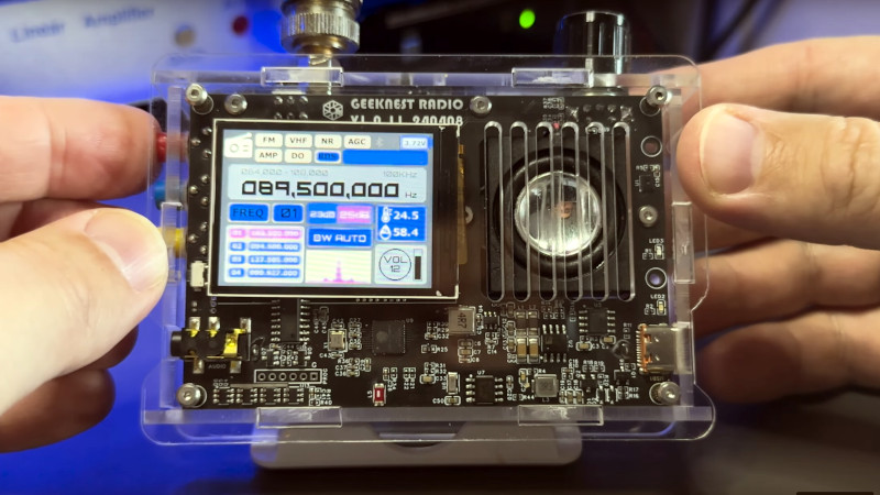
Scanning the firehose of new electronic kits and modules coming from the usual Chinese suppliers can be a rewarding experience, as sometimes among the endless breakout boards comes an item that looks interesting enough to try. As an example there’s a receiver kit being given a quick review by [Tech Minds], offering AM and HF multi-mode, FM broadcast, and air band alongside what appear to be digital streaming features.
Looking at it, though all the RF part is hidden under screening cans we’re guessing it might contain one of the Silicon Labs all-in-one receiver chips, but the whole appears to deliver a useful receiver with a comprehensive interface. The review isn’t quite technical enough so we can’t glean a lot more, but it looks as though it could be useful. We’d be tempted to snag one for review, but since with very few exceptions we pay for the stuff we review, it’s a mite expensive at $50+ for yet another radio.
There’s an ongoing question with all these cheap kits and modules though, first of all where did the design come from and are we freeloading on someone else’s hard work, but then whether or not what you’re getting is a knock-off using defective semiconductors or with bean-counting parts removal degrading performance. We’re guessing more will come out about this radio in due course, and we can all make our own judgement. Meanwhile this one can be found on AliExpress or Banggood, so take a look and see if you’re tempted.
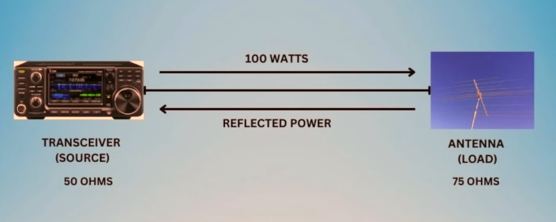
If you are involved in any sort of radio transmission, you probably have at least heard of SWR or standing wave ratio. Most transmitters can measure it these days and most ham radio operators have tuners that measure it, also. But what are you measuring? [KI8R] points out that if your coax has loss — and what coax doesn’t? — you are probably getting an artificially low reading by measuring at the transmitter.
The reason is that most common SWR-measuring instruments pick up voltage. If you measure, for example, 10V going out and 1V going back, you’d assume some SWR from that. But suppose your coax loses half the voltage (just to make an obvious example; if your coax loses half the voltage, you need new coax).
Now, you really have 5V getting to your antenna, and it returns 2V. The loss will affect the return voltage just like the forward voltage. Reflecting 2V from 5 is a very different proposition from reflecting 1V out of 10!
On the other hand, as [KI8R] points out, SWR isn’t everything. In the old days, you’d load your transmitter’s finals into just about anything. Now, solid-state rigs expect to drive a low SWR, or they will crank down the power to prevent the reverse voltage from damaging them.
Overall, it is a good talk about a subject that is often taken for granted. Of course, with cheap VNAs, you can easily measure SWR right at the antenna, often with disappointing results. If you have trouble visualizing standing waves, we know someone who can help.
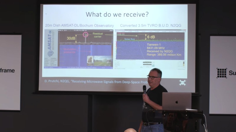
Here’s the thing about radio signals. There is wild and interesting stuff just getting beamed around all over the place. Phrased another way, there are beautiful signals everywhere for those with ears to listen. We go about our lives oblivious to most of them, but some dedicate their time to teasing out and capturing these transmissions.
David Prutchi is one such person. He’s a ham radio enthusiast that dabbles in receiving microwave signals sent from probes in deep space. What’s even better is that he came down to Supercon 2023 to tell us all about how it’s done!
Space Calling
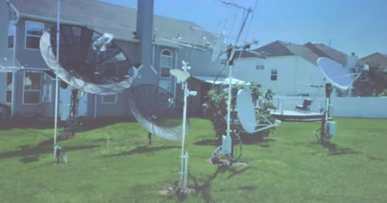
David’s home setup is pretty rad.
David notes that he’s not the only ham out there doing this. He celebrates the small community of passionate hams that specialize in capturing signals directly from far-off spacecraft. As one of these dedicated enthusiasts, he gives us a look at his backyard setup—full of multiple parabolic dishes for getting the best possible reception when it comes to signals sent from so far away. They’re a damn sight smaller than NASA’s deep space network (DSN) 70-meter dish antennas, but they can still do the job. He likens trying to find distant space signals as to “watching grass grow”—sitting in front of a monitor, waiting for a tiny little spike to show up on a spectrogram.
Listening to signals from far away is hard. You want the biggest, best antenna you can get.
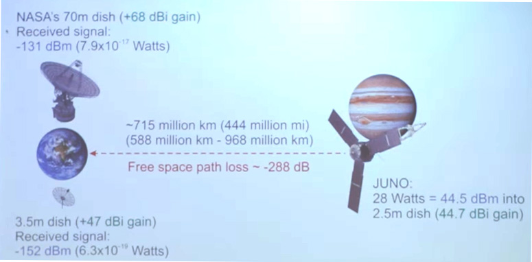
The challenge of receiving these signals comes down to simple numbers. David explains that a spacecraft like JUNO emits 28 watts into a 2.5-meter dish, which comes out to roughly 44.5 dBm of signal with a 44.7 dBi gain antenna. The problem is one of distance—it sits at around 715 million kilometers away on its mission to visit Jupiter. That comes with a path loss of around -288 dB. NASA’s 70-meter dish gets them 68 dBi gain on the receive side, which gets them a received signal strength around -131 dBm. To transmit in return, they transmit around the 50-60 kW range using the same antenna. David’s setup is altogether more humble, with a 3.5-meter dish getting him 47 dBi gain. His received signal strength is much lower, around -152 dBm.
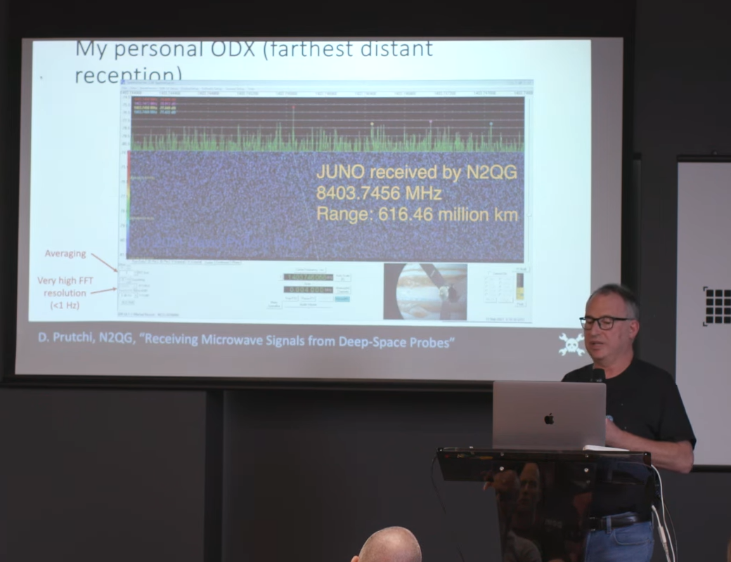
His equipment limits what he can actually get from these distant spacecraft. National space agencies can get full signal from their dishes in the tens-of-meters in diameter, sidebands and all. His smaller setup is often just enough to get some of the residual carrier showing up in the spectrogram. Given he’s not getting full signal, how does he know what he’s receiving is the real deal? It comes down to checking the doppler shift in the spectrogram, which is readily apparent for spacecraft signals. He also references the movie Contact, noting that the techniques in that film were valid. If you move your antenna to point away from the suspected spacecraft, the signal should go away. If it doesn’t, it might be that you’re picking up local interference instead.
THIS. IS. JUST. AWESOME. !!!
This is video decoded from the 8455MHz high rate downlink @uhf_satcom received yesterday. All the work on the decoder and data analysis really paid off in the end!
Video shows solar panel of Chang’e-5 glistening in the sun and dust floating around. pic.twitter.com/FKc92kgskl
Some hobbyists have been able to decode video feeds from spacecraft downlinks.
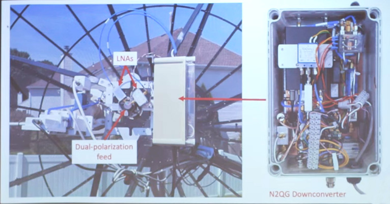
Working at microwave frequencies requires the proper equipment. You’ll want a downconverter mounted as close to your antenna as possible if you’re working in X-Band.
However, demodulating and decoding full spacecraft signals at home is sometimes possible—generally when the spacecraft are still close to Earth. Some hobbyists have been able to decode telemetry from various missions, and even video signals from some craft! David shows some examples, noting that SpaceX has since started encrypting its feeds after hobbyists first started decoding them.
David also highlights the communications bands most typically used for deep space communication, and explains how to listen in on them. Most of it goes on in the S-band and X-band frequencies, with long-range activity focused on the higher bands.
David has pulled in some truly distant signals.
Basically, if you want to get involved in this kind of thing, you’re going to want a dish and some kind of software defined radio. If you’re listening in S-band, that’s possibly enough, but if you’re stepping up into X-band, you’ll want a downconverter to step that signal down to a lower frequency range, mounted as close to your dish as possible. This is important as X-band signals get attenuated very quickly in even short cable runs. It’s also generally required to lock your downconverter and radio receiver to some kind of atomic clock source to keep them stable. You’ll also want an antenna rotator to point your dishes accurately, based on data you can source from NASA JPL. As for finding downlink frequencies, he suggests looking at the ITU or the Australian Communication and Media Authority website.
He also covers the techniques of optimizing your setup. He dives into the minutae of pointing antennas at the Sun and Moon to pick up their characteristic noise for calibration purposes. It’s a great way to determine the performance of your antenna and supporting setup. Alternatively, you can use signals from geostationary military satellites to determine how much signal you’re getting—or losing—from your equipment.
Ultimately, if you’ve ever dreamed of listening to distant spacecraft, David’s talk is a great place to start. It’s a primer on the equipment and techniques you need to get started, and he also makes it sound really fun, to boot. It’s high-tech hamming at its best, and there’s more to listen to out there than ever—so get stuck in!
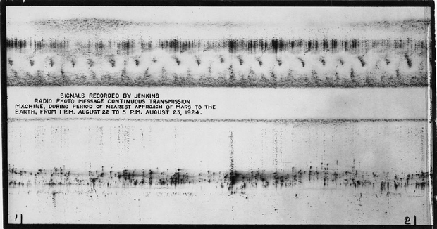
In an age where our gadgets allow us to explore the cosmos, we stumbled upon sounds from a future past: an article on historical signals from Mars. The piece, written by [Paul Gilster] of Centauri Dreams, cites a Times essay published by [Becky Ferreira] of August 20. [Ferreira]’s essay sheds light on a fascinating, if peculiar, chapter in the history of the search for extraterrestrial life.
She recounts an event from August 1924 when the U.S. Navy imposed a nationwide radio silence for five minutes each hour to allow observatories to listen for signals from Mars. This initiative aimed to capitalize on the planet’s close alignment with Earth, sparking intrigue and excitement among astronomers and enthusiasts alike.
Amid the technological optimism of the era, a dirigible equipped with radio equipment took to the skies to monitor potential Martian messages. The excitement peaked when a series of dots and dashes captured by the airborne antenna suggested a “crudely drawn face.” Some scientists speculated that this could be a signal from a Martian civilization, igniting a media frenzy. Yet, skeptics, including inventor C. Francis Jenkins, suggested these results were merely a case of radio frequency interference—an early reminder of the challenges we face in discerning genuine signals from the noise of our own planet.
As we tinker with our devices and dream of interstellar communication, the 1924 incident reminds us that the search for extraterrestrial intelligence is a blend of curiosity, creativity, and, often, misinterpretation.
If you need an amplifier, [Hans Rosenberg] has some advice. Don’t design your own; grab cheap and tiny RF amplifier modules and put them on a PCB that fits your needs. These are the grandchildren of the old mini circuits modules that were popular among hams and RF experimenters decades ago. However, these are cheap, simple, and tiny.
You only need a handful of components to make them work, and [Hans] shows you how to make the selection and what you need to think about when laying out the PC board. Check out the video below for a very detailed deep dive.
To get the best performance, the PCB layout is at least as important as the components. [Hans] shows what’s important and how to best work out what you need using some online calculators.
Using a NanoVNA and a USB spectrum analyzer, [Hans] makes some measurements on the devices using different components, which is very instructive. The measurements lined up fairly well with the theory, and you can see the effects of changing key components in the design.
For as useful as computers are in the modern ham shack, they also tend to be a strong source of unwanted radio frequency interference. Common wisdom says applying a few ferrite beads to things like Ethernet cables will help, but does that really work?
It surely appears to, for the most part at least, according to experiments done by [Ham Radio DX]. With a particular interest in lowering the noise floor for operations in the 2-meter band, his test setup consisted of a NanoVNA and a simple chunk of wire standing in for the twisted-pair conductors inside an Ethernet cable. The NanoVNA was set to sweep across the entire HF band and up into the VHF; various styles of ferrite were then added to the conductor and the frequency response observed. Simply clamping a single ferrite on the wire helped a little, with marginal improvement seen by adding one or two more ferrites. A much more dramatic improvement was seen by looping the conductor back through the ferrite for an additional turn, with diminishing returns at higher frequencies as more turns were added. The best performance seemed to come from two ferrites with two turns each, which gave 17 dB of suppression across the tested bandwidth.
The question then becomes: How do the ferrites affect Ethernet performance? [Ham Radio DX] tested that too, and it looks like good news there. Using a 30-meter-long Cat 5 cable and testing file transfer speed with iPerf, he found no measurable effect on throughput no matter what ferrites he added to the cable. In fact, some ferrites actually seemed to boost the file transfer speed slightly.
Ferrite beads for RFI suppression are nothing new, of course, but it’s nice to see a real-world test that tells you both how and where to apply them. The fact that you won’t be borking your connection is nice to know, too. Then again, maybe it’s not your Ethernet that’s causing the problem, in which case maybe you’ll need a little help from a thunderstorm to track down the issue.