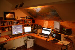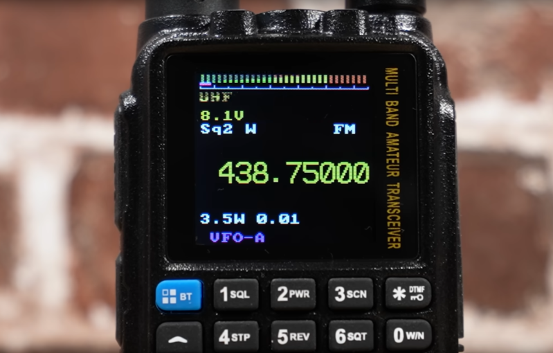
Full disclosure: ham radio isn’t for everyone, and there are many different facets to it. What appeals to one person might bore another to death. One area of ham radio that has changed a lot in the last few years is more or less local and typically mobile operation on VHF or UHF. Not long ago, hams used HTs (walky-talkies or handi-talkies) or mobile radios via repeaters to talk to each other and — the golden prize back then — make phone calls from their cars. Cell phones have made that much less interesting, but there is still an active community of operators talking on repeaters. However, the traffic has gone digital, the Internet is involved, and people with inexpensive, low-powered radios can talk to each other across the globe. This is nothing new, of course. However, having digital services means that operators with special interests can congregate in what amounts to radio chat rooms organized by region or topic.
There’s a long history of people listening to ham radio conversations with shortwave radios, SDRs, and scanners. But with so much activity now carried on the Internet, you can listen in using nothing more than your web browser or a phone app. I’ll show you how. If you get interested enough, it is easy enough to get your license. You don’t need any Morse code anymore, and a simple Technician class license in the United States is all you need to get going.
A Quick DMR Primer
There are several digital ham networks around and like real networks, you can have different physical transport layers and then build on top of that. For the purposes of this post, I’m going to focus on DMR (digital mobile radio) on the Brandmeister network which is very large and popular ham network. You won’t need a license nor will you need to sign up for anything as long as you are content to just listen.
Here’s how it works: Brandmeister operates a large number of servers worldwide that communicate with each other and provide calling services, including group calls. So, if we set up a Hackaday talk group (fictitious, by the way) on group 1337, interested people could connect to that talk group and have a conversation.
Since we are just going to listen, I’m going to skip some of the details, but the trick is how people get to talk to these networks. In general, there are three ways. The classic way is to use a digital radio to talk to a repeater that is connected to the network. The repeater may have one or more talk groups on all the time, or you might request access to one.
However, another way to connect your radio to a “hotspot” connected to the Internet. That is, more or less, a special form of repeater that is very low power, and you have complete control over it compared to a repeater on some faraway hill. However, if you don’t mind operating using just a computer, you don’t need a radio at all. You simply talk directly to the nearest server, and you are on the network. Some of your audio will go to other computers, and it may go over the airwaves via someone else’s hotspot or repeater.
Talk Groups
The Brandmeister website has a lot of info and you don’t need to be logged in to see it. Head over to their site and you’ll see a lot of info including a network map and statistics about repeaters and hotspots. You can get an idea of who has been talking lately by clicking Last Heard link. While this is interesting, it isn’t as interesting as you’d think, because you really want to focus on talk groups, not individual users.
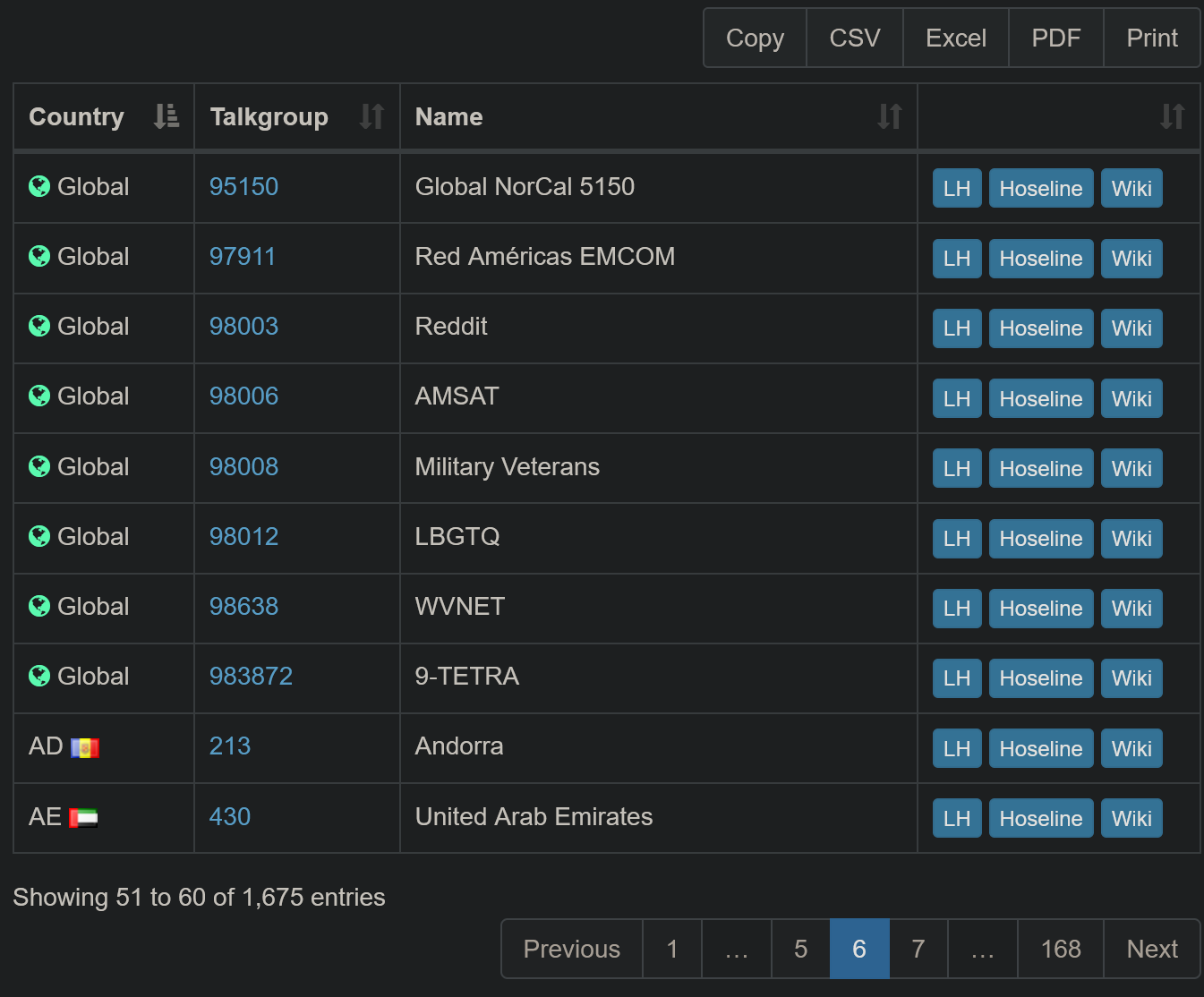
To see a list of all the talk groups on the system, you can click Information and then Talkgroups. You can filter the list and you can also download the dataset in different formats if you want to browse it in a different format.
There are three buttons on each row of the database. The LH button shows you the last heard stations for that group. The Wiki button takes you to a Wiki page that, for some groups, has more information about it. But the really interesting button is the one marked Hoseline. You can also open the Hoseline directly which is what I usually do.
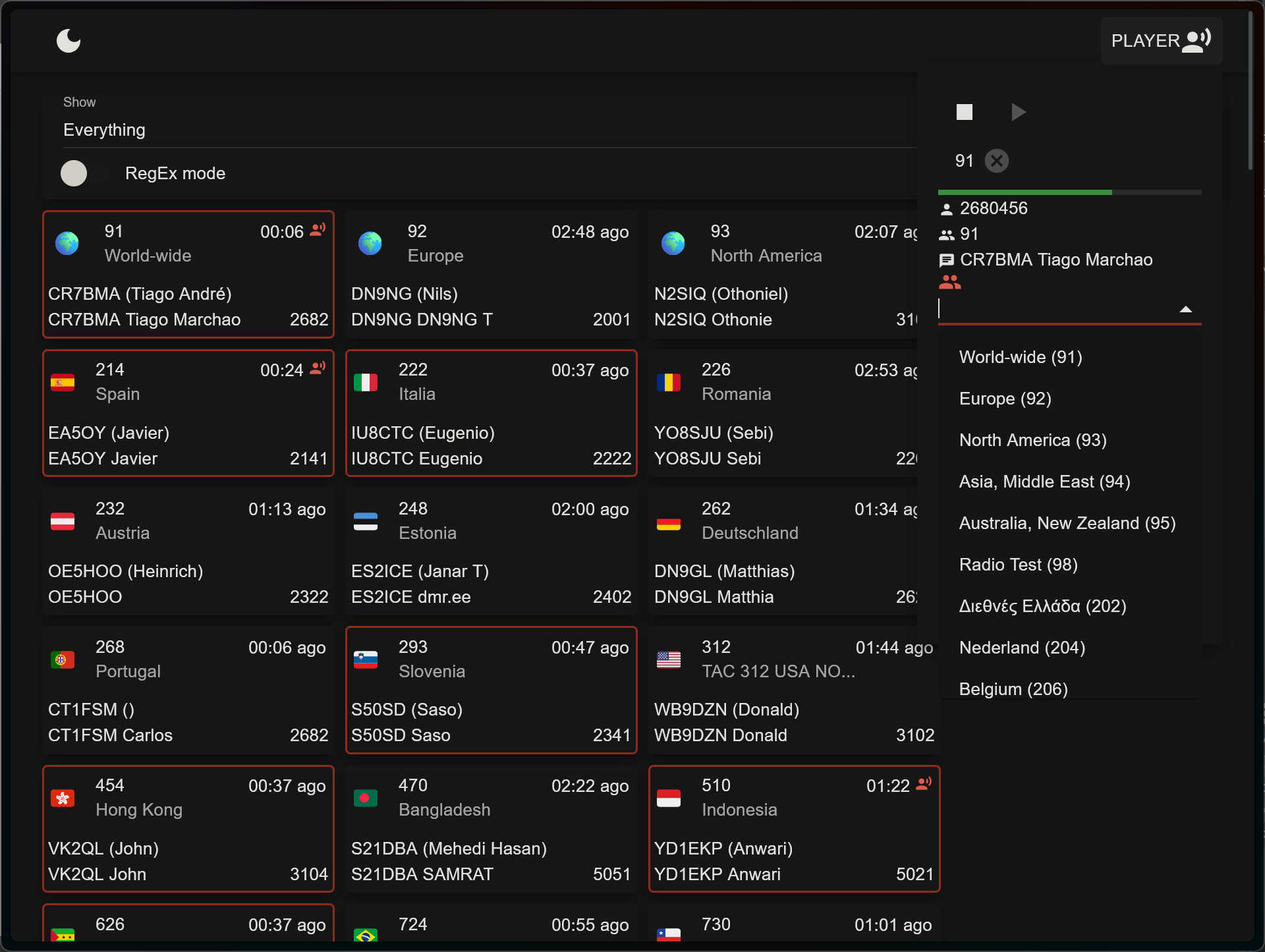
What’s the Hoseline? It shows activity across the network as a bunch of boxes indicating recently active talk groups. Boxes with red lines around them have people actively talking on them. The others have been recently active. It is visually interesting, yes, but that’s not the big selling point.
If you click on a box, you will hear the activity on that talk group. That’s all there is to it.
Overwhelming
There are a lot of talk groups. You can filter at the top left part of the page where it says “Everything.” You’ll have to drop the list down and unselect Everything. Then, you can select any countries or areas you want to follow. If you are brave, you can click RegEx mode and enter regular expressions to match talk group numbers (e.g. ^310.*).
The “Player” button at the top right gives you more control. You can add multiple groups from a list, see information about who is talking, and stop or start the audio.
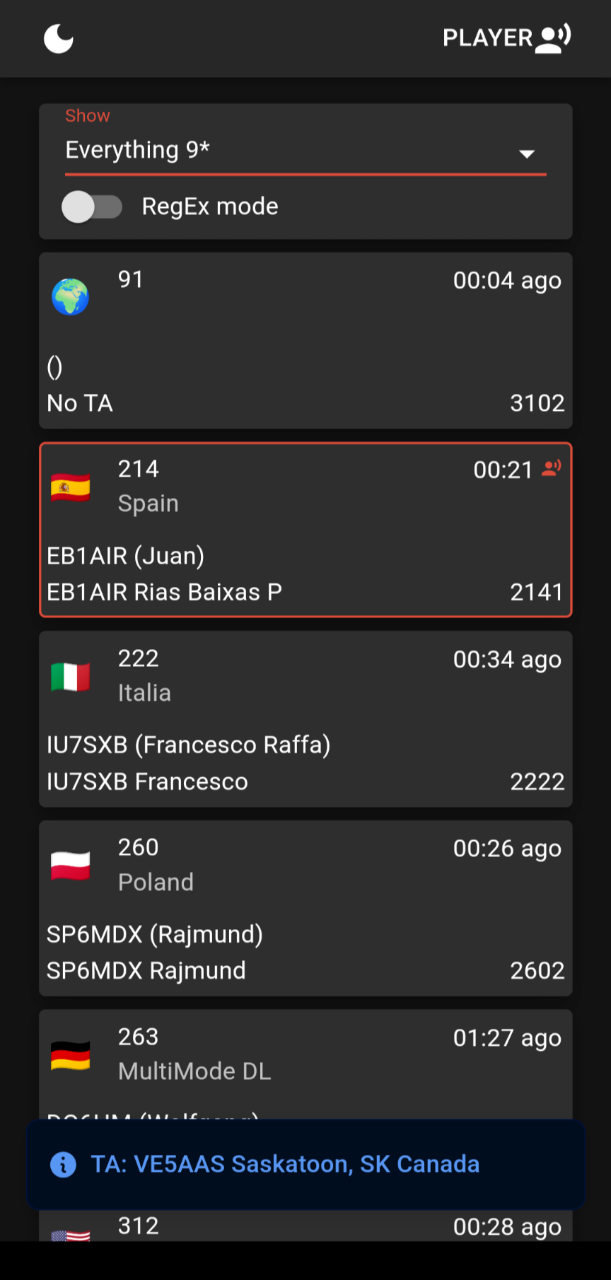
If you prefer to do your listening mobile, you can also get the hoseline on your Android device. Just install the app, and you’ll find it works the same way.
Finding Something Interesting
Lord Nelson once said, “The greatest difficulty in war is not to win the battle, but to find the enemy.” That’s accurate here, too. Finding an interesting conversation out of all those talk groups is somewhat a needle in a haystack. A quick look around at the talk group lists might help.
The 91 and 93 groups stay busy but generally with short exchanges since they cover a wide area. The USA bridge at 3100 sometimes has traffic, too.
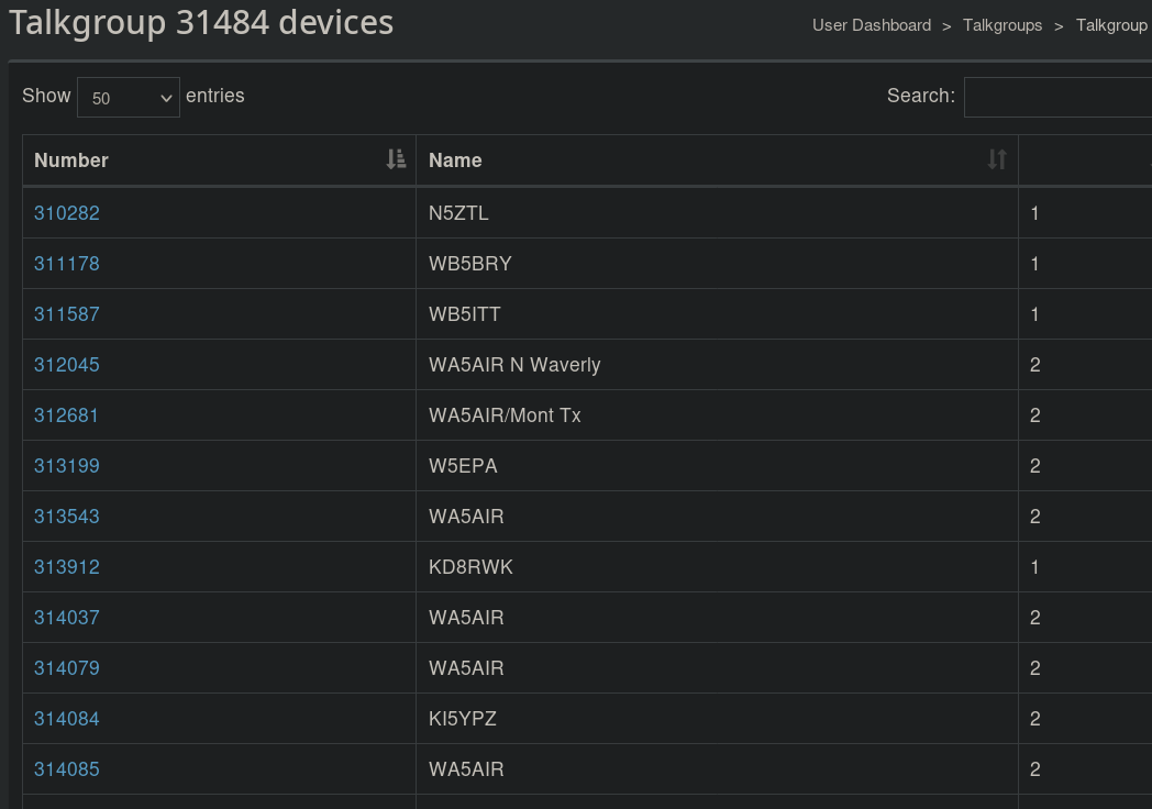
If you look at the group’s listing on the Web, you can click the group number and see what stations are connected to it. Keep in mind, some of these may be repeaters or gateways that could have no one on the other side, or could have dozens of people on the other side. But it can give you an idea if the talkgroup has any users at all.
You can also search the Internet for DMR nets and repeaters. Sometimes, it is interesting to listen to local repeaters. Sometimes, it is fun to listen to repeaters in other places. Want to find out what’s going on at your next vacation spot? Practice your French?
You can find many DMR repeaters using the RepeaterBook search page. There are also man lists of DMR nets.
Next Steps
There are many other similar networks, but they may not have a way to listen that doesn’t require some software, registration, or licenses. There’s plenty on Brandmeister to keep you busy. If you worry about people listening in, that’s no different than regular radio has been since the beginning.
You can always get your ham license and join in. Even without a radio, there are ways to talk on the network. [Dan Maloney] has advice for getting your “ticket.” It is easier than you think, and you can do a lot more with a license, including talking through satellites, sending TV signals over the air, and bouncing signals of meteors or the moon. If you want to listen to more traditional ham radio in your browser, try a Web-based SDR.

 Een Duitse hacker heeft een satelliet tot leven weten te wekken die sinds 2013 niet meer werkte. Daarvoor hoefde PistonMiner niet naar de ruimte; de satelliet kon vanaf de grond weer worden gerepareerd door eerst de telemetrie te herstellen en daarna de originele code te hacken.
/i/2007162470.png?f=imagenormal)