Before swearing my fealty to the Jolly Wrencher, I wrote for several other sites, creating more or less the same sort of content I do now. In fact, the topical overlap was enough that occasionally those articles would get picked up here on Hackaday. One of those articles, which graced the pages of this site a little more than seven years ago, was Getting Started with RTL-SDR. The original linked article has long since disappeared, and the site it was hosted on is now apparently dedicated to Nintendo games, but you can probably get the gist of what it was about from the title alone.
When I wrote that article in 2012, the RTL-SDR project and its community were still in their infancy. It took some real digging to find out which TV tuners based on the Realtek RTL2832U were supported, what adapters you needed to connect more capable antennas, and how to compile all the software necessary to get them listening outside of their advertised frequency range. It wasn’t exactly the most user-friendly experience, and when it was all said and done, you were left largely to your own devices. If you didn’t know how to create your own receivers in GNU Radio, there wasn’t a whole lot you could do other than eavesdrop on hams or tune into local FM broadcasts.
Nearly a decade later, things have changed dramatically. The RTL-SDR hardware and software has itself improved enormously, but perhaps more importantly, the success of the project has kicked off something of a revolution in the software defined radio (SDR) world. Prior to 2012, SDRs were certainly not unobtainable, but they were considerably more expensive. Back then, the most comparable device on the market would have been the FUNcube dongle, a nearly $200 USD receiver that was actually designed for receiving data from CubeSats. Anything cheaper than that was likely to be a kit, and often operated within a narrower range of frequencies.
Today, we would argue that an RTL-SDR receiver is a must-have tool. For the cost of a cheap set of screwdrivers, you can gain access to a world that not so long ago would have been all but hidden to the amateur hacker. Let’s take a closer look at a few obvious ways that everyone’s favorite low-cost SDR has helped free the RF hacking genie from its bottle in the last few years.
Hardware Evolution
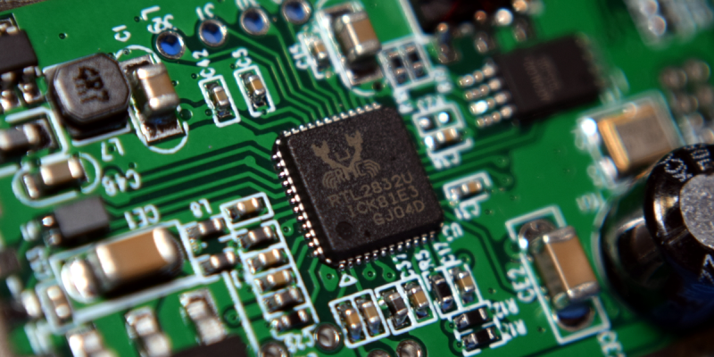
Even though the project is called RTL-SDR, the Realtek RTL2832U chip is in reality just half of the equation; it’s a USB demodulator chip that needs to be paired with a tuner to function. In the early days, there were a number of different tuners in use, and figuring out which one you were getting was a pretty big deal. The Elonics E4000 was the most desirable tuner as it had the widest frequency range, but it could be difficult to know ahead of time what you were getting.
The packaging and documentation were all but useless; either the manufacturer didn’t bother to include the information, or if they did, it would often become outdated as new revisions of the product were produced. The only way to be sure about what you were getting was to see if somebody had already purchased that particular model and reported on their findings. Luckily, the tuners were cheap enough that you could buy a couple and experiment. In those days, it wasn’t uncommon to find RTL-SDR compatible devices for less than $10 from import sites.


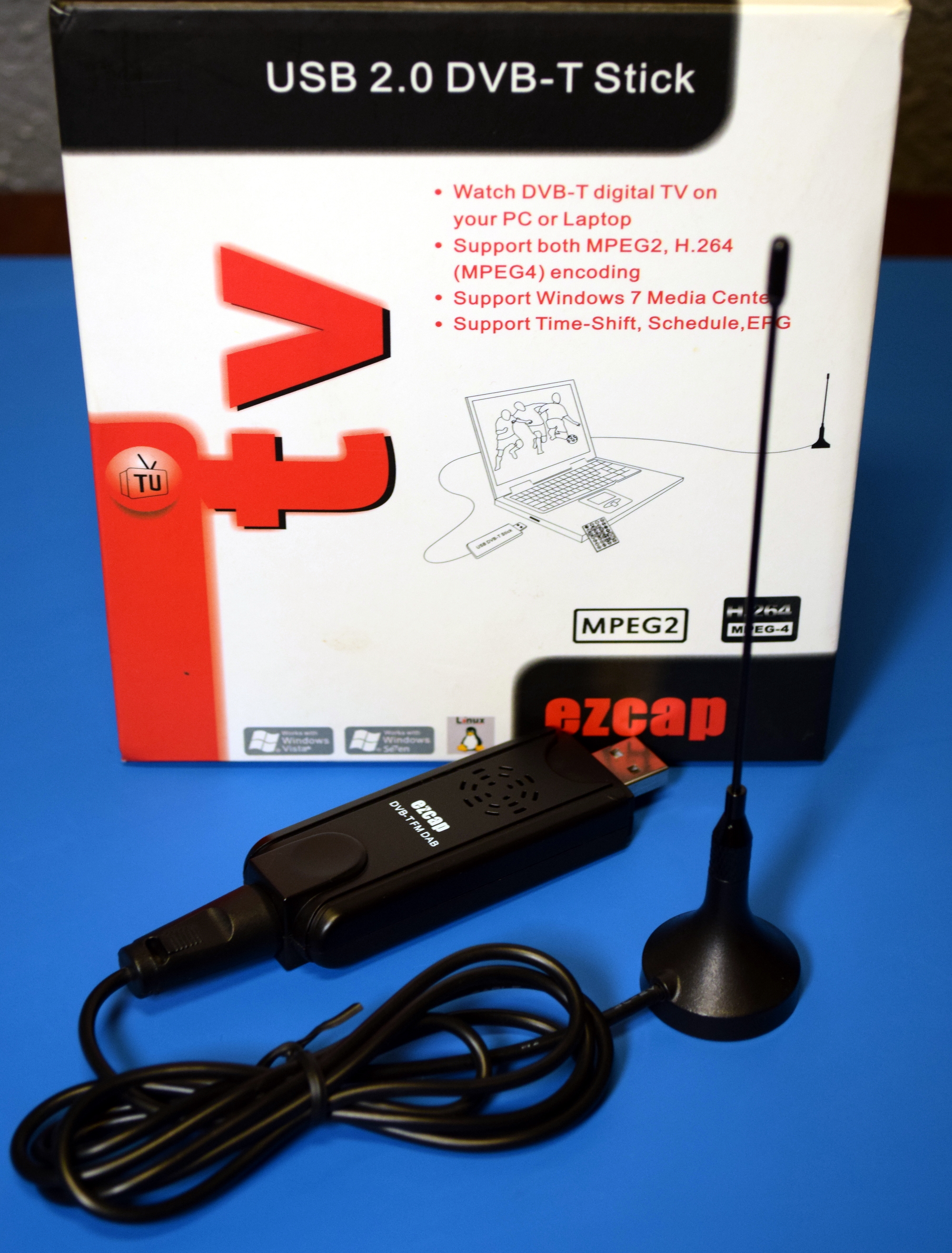
Opening up a contemporary RTL2832U+E4000 receiver, we can see they were relatively simple affairs. The flimsy plastic case doesn’t do much to prevent interference, and the Belling-Lee connector connector is intended for use with a traditional TV antenna. Note this particular model features an IR receiver so the user could change TV channels with the included remote; a reminder of what this device was actually built for.
These days, you don’t need to wade through pages of nearly identical looking USB TV tuners to find compatible hardware. There are now several RTL2832U-based receivers which are specifically designed for RTL-SDR use, generally selling for around $30. These devices not only address the shortcomings of the original hardware offerings, but in many cases add in new capabilities that simply wouldn’t have made sense to include back when they were just for watching TV on your computer.


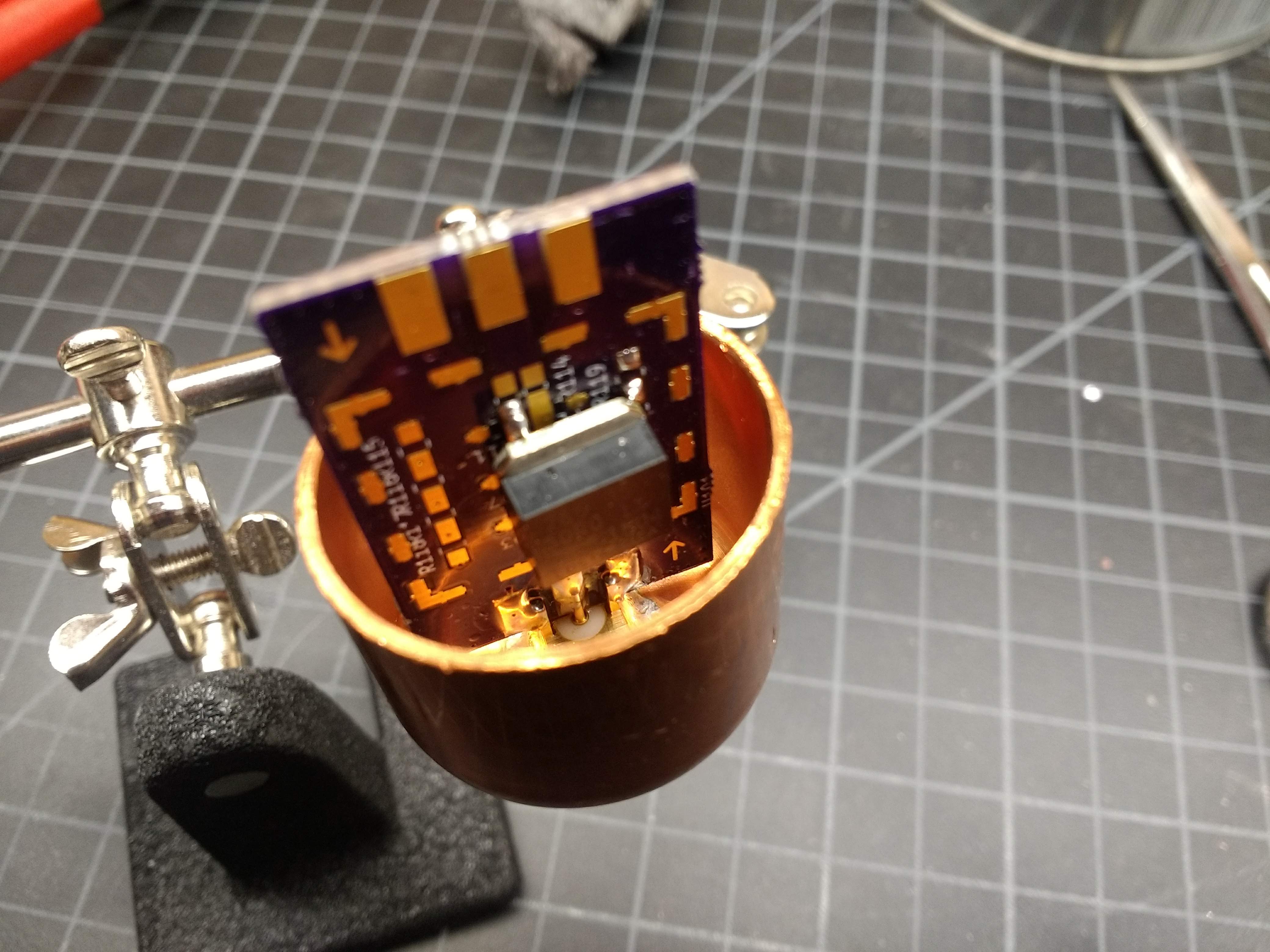
Here we have the “RTL-SDR Blog v3” receiver, which is one of the most popular “next generation” RTL-SDR receivers. The plastic case has been replaced with an aluminum one that not only reduces interference, but helps the board dissipate heat while in operation. The crystal has been upgraded to a temperature compensated oscillator (TCXO) which helps reduce temperature drift. The R820T2 tuner is paired with a standard SMA antenna connector, and both it and the RTL2832U have some unused pins broken out if you’re looking to get into developing modifications or expansions to the core hardware.
Software Library
The improvements to the base RTL-SDR hardware are welcome, and it’s nice to not have to worry about whether or not the receiver you’ve purchased is actually going to work with the drivers, but realistically those changes mainly benefit the more hardcore users who are pushing the edge of the envelope. If you’re just looking to sniff some 433 MHz thermometers, you don’t exactly need a TCXO. For most users, the biggest improvements have come in the software side of things.
For one, the RTL-SDR package is almost certainly going to be in the repository of your favorite GNU/Linux distribution. Unless you need some bleeding edge feature, you won’t have to compile the driver and userland tools from source anymore. The same will generally be true for the SDR graphical frontend, namely gqrx by Alexandru Csete. Those two packages are enough to get you on the air and browsing for interesting signals, but that’s just the beginning. The rise of cheap SDRs has inspired a number of fantastic new software packages that are light-years ahead of what was available previously.
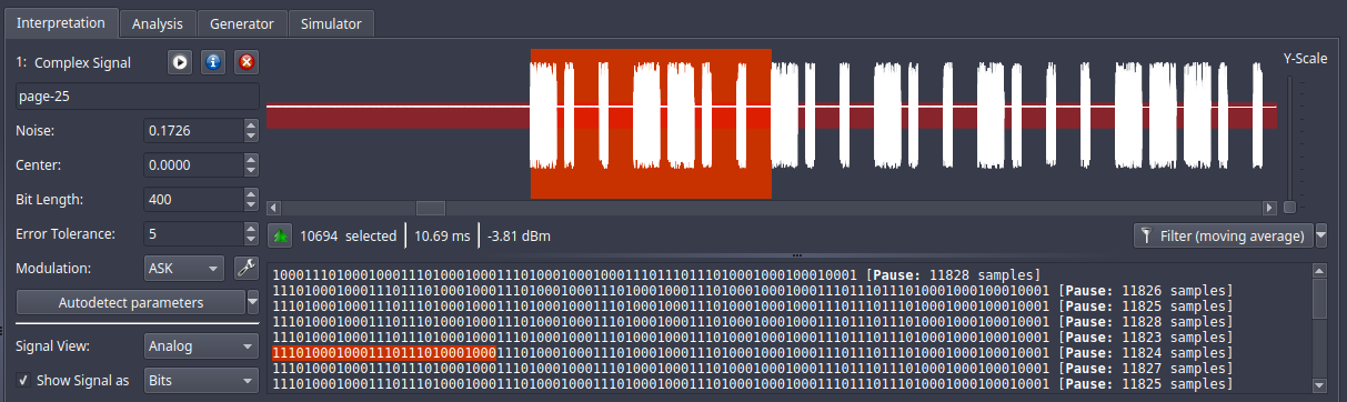
Certainly one of the best examples is Universal Radio Hacker, an all-in-one tool that lets you search for, capture, and ultimately decode wireless signals. Whether it’s a known protocol for which it already has a built-in decoder, or something entirely new that you need to reverse engineer, Universal Radio Hacker is a powerful tool for literally pulling binary data out of thin air. Those looking to reverse unknown wireless protocols should also take a look at inspectrum, another tool developed in the last few years that can be used to analyze captured waveforms.
If you’re more interested in the practical application of these radios, there have also been a number of very impressive “turn-key” applications developed that leverage the high availability of low-cost SDRs. One such project is dump1090, a ADS-B decoder that was specifically developed for use with the RTL-SDR. With a distributed network of receivers, the software has allowed the community to democratize flight tracking through the creation of open data aircraft databases.
The Gift of Inspiration
In the years since its inception, the RTL-SDR project has become the de facto “first step” for anyone looking to experiment with radio. It’s cheap, it’s easy, and since the hardware is incapable of transmission, you don’t have to worry about accidentally running afoul of the FCC or your local equivalent. Honestly, it’s difficult to think of a valid reason not to add one of these little USB receivers to your bag of tricks; even if you only use it once, it will more than pay for itself.
Ultimately, this is the greatest achievement of the RTL-SDR project. It drove the entry barrier for radio experimentation and hacking so low that it’s spawned a whole new era. From the unique vantage point offered by Hackaday, we can see the sharp uptick of RF projects that correspond to the introduction of an easy to use and extremely affordable software defined radio. People who might never have owned a “real” radio beyond the one in their car can now peel back the layers of obscurity that in the past kept the vast majority of us off the airwaves. This is a very exciting time for wireless hacking, and things are only going to get more interesting from here on out. Long live RTL-SDR!

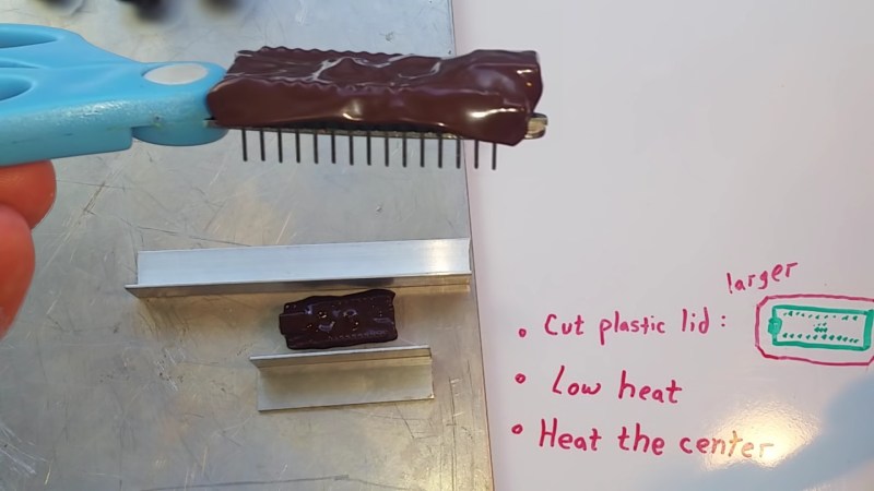
 your magic smoke. Even if you are lucky, stray parts are the root of boundless malfunctions from disruptive to deadly. [TheRainHarvester] shares his trick for


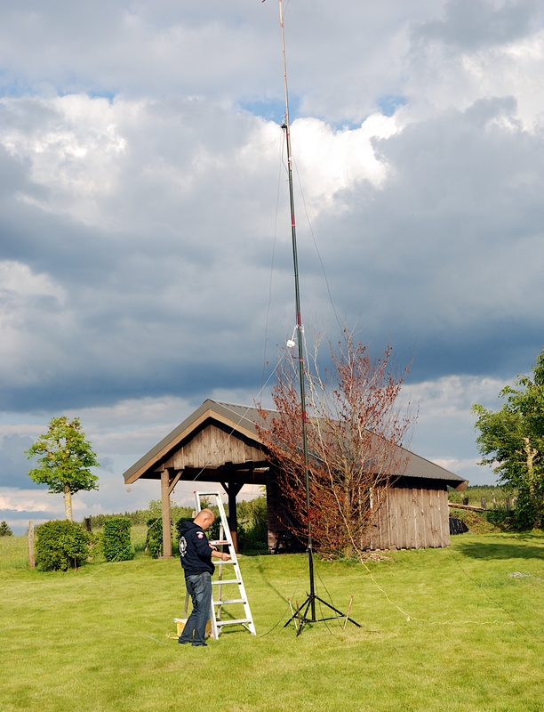
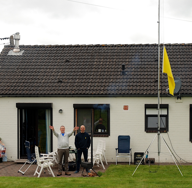


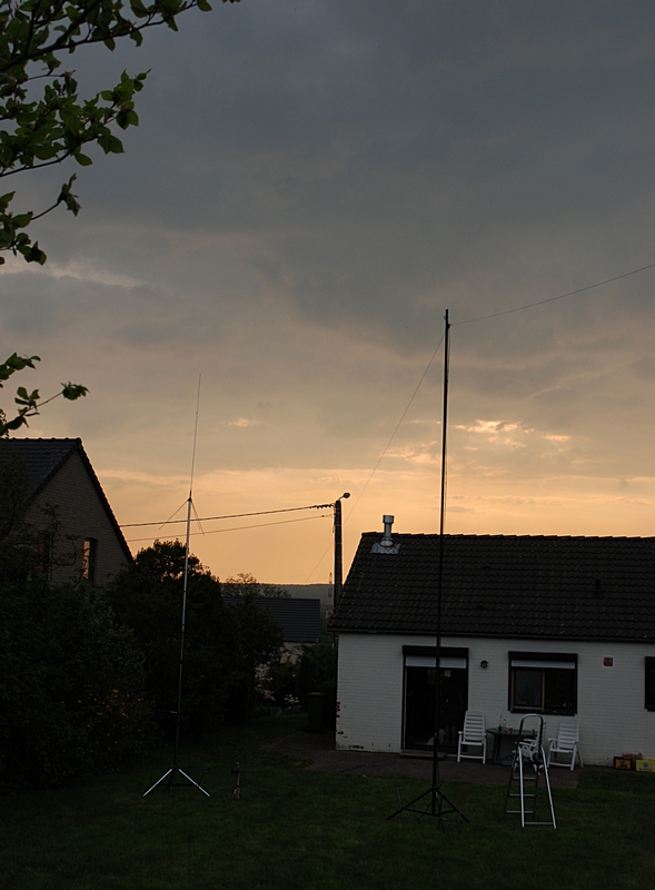
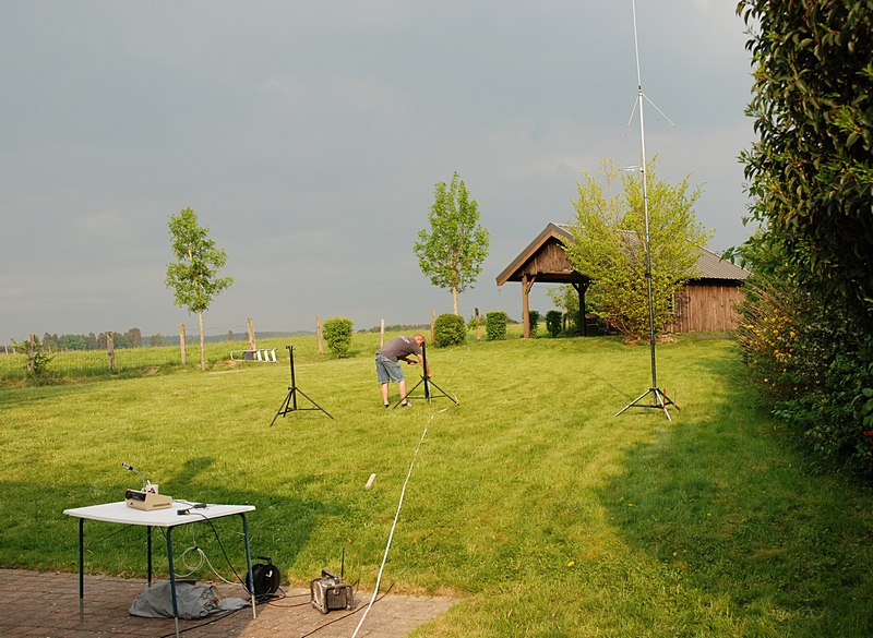
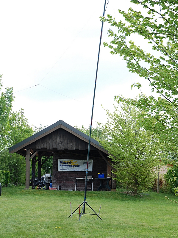
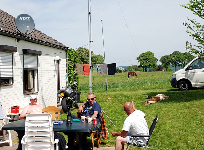
 Net als vorig jaar zullen er een aantal antennes worden opgesteld voor de gebruikelijke HF banden en natuurlijk 2m en 70cm. Op die laatste band staat ON0TB altijd standby op 439.0125 MHz. De repeater PI3ZLB is vanuit Dairomont waarschijnlijk niet bereikbaar…
 De velddag is natuurlijk ook door anderen te bezoeken. Hou er wel rekening mee dat er voor de maaltijden niet is gerekend op mee-eters dus zorg zelf voor eigen eten, indien nodig. Er zijn supermarkten genoeg in de buurt voor ad-hoc voedselvoorzieningen. Voor de consumpties wordt een bijdrage gevraagd. Wil je langs komen? Van harte welkom! Meld je even in via de repeater van Botrange: 439.0125 MHz (shift -7.6MHz), die staat continu aan tijdens de velddag. Nog beter: meld je vooraf aan tijdens een van de clubavonden en spreek af wanneer je komt zodat er rekening met je kan worden gehouden.