 Even as the current sun spot cycles do not favor radio operation in the HF band (defined here as 1.5 to 30 MHz), there are military and amateur radio applications for 20 W battery-operated radios with whip antennas. In general, the whip antenna which makes the radio portable is not optimized for signal propagation: a whip antenna has no ground return or proper counterpoise. While some users drag a wire up to 8 m behind, this is not an ideal solution.1-2
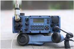
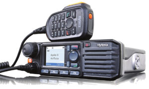
This article explores optimizing antenna performance for HF and VHF (defined here as 30 to 108 MHz) manpacks using an antenna tuning unit (ATU). Two Rohde & Schwarz battery-operated manpacks with internal ATUs were used for testing, comparing their internal ATUs with the performance obtained using external tuners. The two R&S units are multiband, multirole and multimode software-defined radios (SDR), covering HF and VHF (R&S®MR3000H) and 25 to 512 MHz (R&S®MR3000U, shown in Figure 1). They are similar to other HF, VHF and UHF transceivers popular with radio amateurs.
Figure 1 R&S®MR3000U manpack radio, covering 25 to 512 MHz.

Figure 2 Original dipole made by Heinrich Hertz in 1887 used balls at each end to form a capacitive load (Source: Deutsches Museum in Munich).
SHORT ANTENNAS
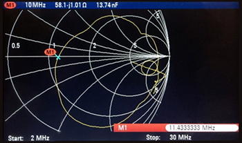
Figure 3 Measured impedance of a 2 x 5 m non-resonant dipole antenna from 2 to 30 MHz.
The first resonant dipole antenna, developed by Heinrich Hertz in 1887, was driven from a “noisy” spark gap transmitter (see Figure 2). Both sides were equally long and used end-loading metal balls, acting as a capacitive device to reduce the length of the two λ/4 resonant segments.3
Now consider a symmetrical, non-resonant dipole, each side 5 m long, with the center point connected to a battery-operated network analyzer approximately the same size and surface area as a manpack. The analyzer is connected to the symmetrical dipole with a mechanically small, 1:1 symmetrical-to-asymmetrical ferrite transformer covering 1 to 60 MHz. Figure 3 shows the measured impedance of the antenna from 2 to 30 MHz, which covers both tactical military and some amateur radio bands. The typical mobile/portable application using a vertical antenna reflects the evolution of the dipole to a monopole: a symmetrical two-wire antenna made asymmetrical with a transformer and best performing with a set of resonant radials and a counterpoise or some kind of grounding.
The magnetic field of the antenna is generated by RF current in the antenna wire or rod, perpendicular to the antenna. The electric field of the antenna is needed for resonance. Many antennas are bent at the end to make them mechanically smaller. An extreme example is the capacitive hat; another is a “loading” coil located about two-thirds of the length – although this reduces the usable bandwidth.
The electrical equivalent of an electrically short antenna is given by
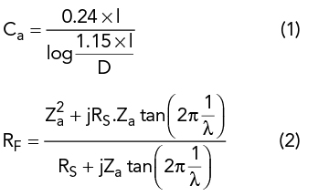
where Ca is the equivalent capacitance of the antenna in pF, D is the diameter of the wire, RF the input-output impedance of the λ/4 antenna, RS the radiation resistance, Za the characteristic impedance of the wire and l the length of the element.
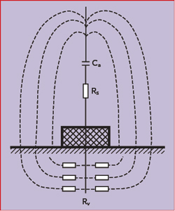
Figure 4 Vertical antenna showing the current loop through the ground.
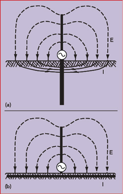
Figure 5 A poor ground near the antenna’s base results in losses from the return current (a), while a ground network or counterpoise reduces the losses (b).4
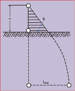
Figure 6 Current distribution in a short antenna, including the ground current.3
Grounding is necessary to close the loop for the currents. Figure 4 illustrates the behavior of the electric field lines for a vertical antenna over ground. The field lines penetrate the surface of the Earth and produce a current that flows back to the ground point, incurring heat losses. The antenna’s efficiency, η, is defined as
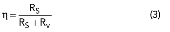
where RS is the radiation resistance and Rv the total effective loss resistance. For electrically short antennas with radiation resistance values of only a few ohms, the resulting antenna efficiency can be very low, especially with long-wave and extremely long-wave communication systems. In such cases, Rv can be reduced with a ground network or a wire network extending over the ground as a counterpoise, especially with unfavorable ground conditions (see Figure 5). All symmetrical antennas not excited with respect to ground, such as dipoles, benefit from the antenna’s independence from the ground resistance – as long as the entire antenna is elevated above the ground.
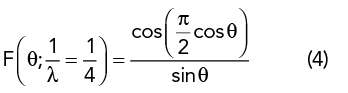
Electrically short antennas, typically λ/10 or shorter, look like a capacitor with a typical capacitance of 25 pF/m of length, e.g., 75 pF for a 3 m rod. At 2 MHz, where the wavelength is 150 m, an inductor of 84 μH is required for resonance. The radiation comes from the current in the antenna, not from the voltage; the voltage is maximum at the end. To better understand the radiation, consider the case where the whip antenna’s length, l, is λ/4. The vertical radiation pattern of the antenna over ground is1,3
The radiated power, RF current and radiation resistance of the λ/4 antenna over ground is determined from the power radiated in the half sphere. Solving for RS:
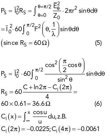
where C is Euler’s constant (0.5772) and Ci(x) is the cosine integral. The radiation resistance of the electrically short antenna based on the electric field can be calculated from:
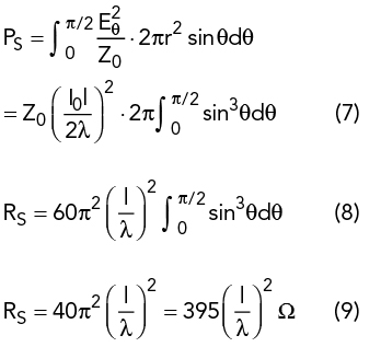
The radiation resistance of the short antenna is obviously very low.
EFFECTIVE HEIGHT
To calculate the effective height of an electrically short antenna, consider that the open circuit voltage, V0, of the antenna is proportional to the antenna field strength, E, where the antenna is located:
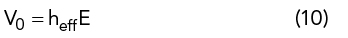
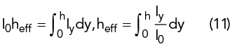
The proportionality factor heff has the dimension of length and is known as the effective height. If the current in the antenna is independent of location (i.e., a Hertzian dipole), then heff corresponds to the antenna’s geometrical length, l. Otherwise, the effective height will be less because of the non-uniform current distribution. In the general case, heff is determined by converting the current area into a rectangle with the same area and the maximum current, I0, at its base (see Figure 6). Its height is then equal to heff. Computationally,
The effective height is related to the effective area, A, and characteristic impedance Z03-4 as follows:
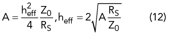
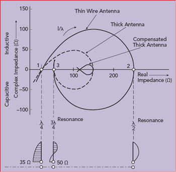
Figure 7 Theoretical input impedance of three wire antennas with different diameters.4
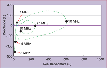
Figure 8 Measured impedance of a 35 ft. whip antenna used on a ship.5
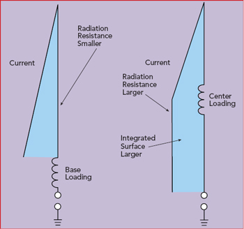
Figure 9 Center loading a whip antenna creates a larger integrated surface for the current than base loading, which improves radiation.6 The two figures are not to scale.
Figure 7 shows the differences in theoretical impedance of wire antennas with different wire diameters. Figure 8 plots the measured impedance versus frequency of a 35 ft. long whip antenna, showing the maximum real impedance is approximately 600 Ω at 10 MHz (λ/2), and the real loss resistor is never below 10 Ω. The imaginary part of the impedance is −400 Ω at 2 MHz and approximately 200 Ω at 9 MHz.
ANTENNA LOADING AND TUNING
Where a whip antenna is loaded affects the antenna’s performance. Figure 9 compares base and center loading. With center loading, both the radiation resistance and integrated surface are larger, which are better for radiation.
The typical lowpass configuration for antenna tuning is a series L, shunt C network, also called a Collins filter (see Figure 10). For the 35 ft. whip antenna operating at 2 MHz (Figure 8), the network needs an inductor of 100 μH and a shunt capacitor of 262 pF. Assuming a 4:1 input transformer and the sum of the radiation and ground loss resistance to be larger than 12.5 Ω (50/4), the tuner only needs two variable elements, and either the left or right capacitor bank in the figure can be eliminated. The right capacitor bank is used when the load resistance is greater than 50 Ω (12.5 Ω using the 4:1 transformer), and the left capacitor bank is used when the load resistance is less than 50 Ω (12.5 Ω using the 4:1 transformer). In this case, at 2 MHz, R = 12 and Xc = −400 Ω, the required series inductor will be 33.42 μH and the left capacitor bank is used to set a value of 3.18 nF. The most inductive impedance is at 9 MHz, approximately 600 +j200 Ω, such that 25 μH and 370 pF are needed for tuning.
The inductances for tuning are found in commercial input/output switchable antenna tuners operating from 1.5 to 30 MHz. The tuning network looks like an “L,” where the switched shunt capacitors can be connected to either side of the inductors.7 Figure 11a shows the matching ranges of the tuner with the capacitors on each side of the inductors, and Figure 11b shows a simplified schematic of the main capacitor bank that is switched to either the input or output side of the inductors. The inductors are wound with 0.048 in. diameter, enameled copper wire and have approximately 0.04 μH step size. The capacitor step size is 9.375 pF. This tuner has nine switchable inductors, 10 switchable capacitors and two positions for one of the capacitor banks (i.e., on either side of the inductors), yielding 1,048,576 tuning combinations. The 6 pF capacitor at the output represents the ceramic antenna mount or connector. For best performance, antenna tuners use air core coils or very low permeability powdered iron cores. As such, some of the measured intermodulation distortion (IMD) products result from ferrite saturation, not from the power amplifier driving the antenna.8-9
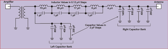
Figure 10 Schematic of a Collins antenna tuner with an input transformer.
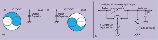
Figure 11 Tuner matching options: the right capacitor bank is used when the load resistance is > 50 Ω, and the left capacitor bank is used when the load resistance is < 50 Ω (a). Tuning network similar to that of the ICOM AT130 (b).
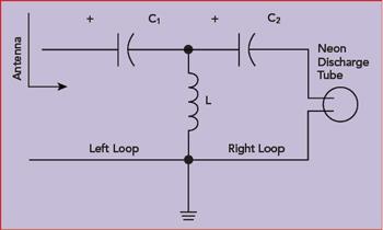
Figure 12 T-configuration ATU.
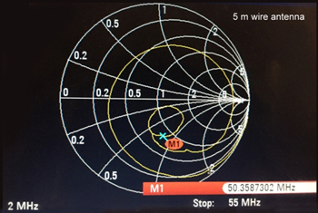
Figure 13 Measured S11 of a 5 m wire antenna with 8 m ground wire, 2 to 55 MHz.
Occasionally, a tuner design uses a highpass, T-configuration rather than a π (see Figure 12). The LC1 forms one resonant circuit, LC2 forms the other circuit and the two are tuned to the resonant frequency. The left loop and the right loop are dependent. Generally, when the value of C2 is too small, input resonance occurs yet there is no loading and no output power obtained. This is the flaw of the design: the highpass filter is mathematically over-determined. The left loop can be in resonance, and no output power (voltage) is available in the right loop. Other drawbacks of this frequently-used design are higher loss, the lack of harmonic suppression and LC combinations where the tuner absorbs most, if not all, the power without tuning the antenna perfectly.6 For electrically short antennas, this can be overcome with a voltage probe at the output, such as a pre-ignited neon bulb. The neon discharge tube glows when there is maximum voltage at the output of capacitor C2. If the frequency is below 30 MHz, a blue color is emitted; if the frequency is above 30 MHz, a pinkish color is emitted.
2 MHz TUNING
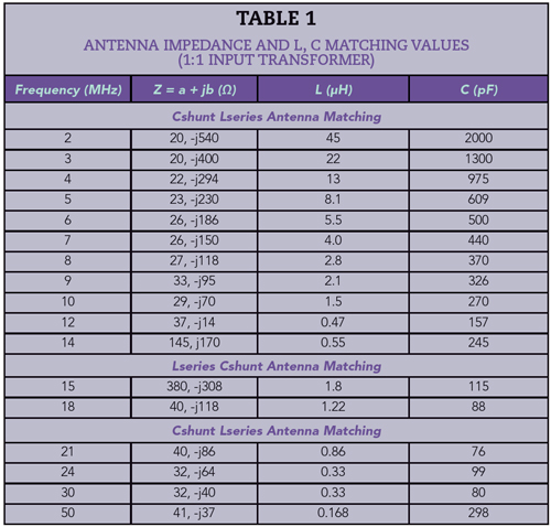
For a 5 m wire antenna with an 8 m ground wire and π tuner, Figure 13 shows the measured antenna impedance, and Table 1 summarizes the antenna impedance and the L and C values needed for matching, assuming a 1:1 (50 Ω) input transformer.10-11 The LC combination minus the capacitance value of the antenna rod or wire must resonate at the test frequency. Figure 14 shows the antenna resonance tuning at 2 MHz, and Figure 15 shows the simulated Z11 vs. frequency, with Re{Z11} plotted in Figure 15a and Im{Z11} in Figure 15b. The lower curve in Figure 15a closely matches the desired 20 Ω at 2 MHz; however, it assumes no losses in the tuner. The upper curve, assuming a realistic Q of 200, shows 22 Ω at 2 MHz. As power is I2R, a 10 percent increase in Re{Z11} causes a power loss of approximately 10 percent, from 20 to 18 W available for radiation. These losses are frequently overlooked. While the two-element tuning network produces the desired real and imaginary values, the 8 m ground wire is too short at this frequency, so there is no useful grounding.
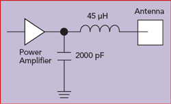
Figure 14 Resonance tuning for the 5 m wire antenna with 8 m ground wire at 2 MHz.
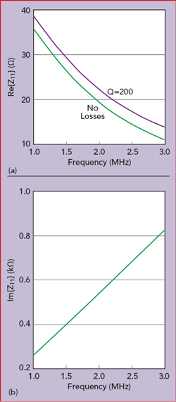
Figure 15 Simulated Re{Z11} (a) and Im{Z11} (b) at 2 MHz.
GROUNDING
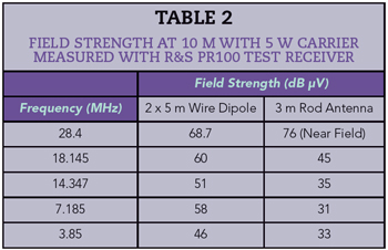
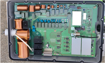
Figure 16 ICOM antenna tuner with 90 degree offset coils.
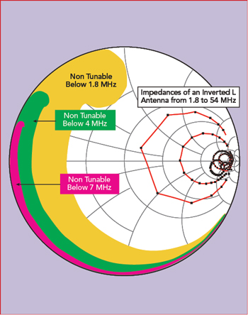
Figure 17 Tuning range of ICOM AH4 antenna tuner.13
An antenna tuner can improve the matching but not the radiation. At a single frequency, the asymmetric dipole shows a resonance close to 12 MHz, the antenna to case impedance is 37 Ω – almost purely resistive – and the system works. A symmetrical, non-resonant antenna like an inverted V with an elevated tuner and an asymmetrical antenna cable isolating the radio and RF, by actually grounding it, will give superior results. If this is not possible, to obtain a symmetrical antenna system a ground connection to some electrical wire, fence or similar structure is recommended. If the built-in antenna tuner can tune end-fed, high impedance, low current, long wires, this may be a good solution, although the radio is no longer a manpack, more of a portable solution for a stationary setup. Some counterpoise is needed for good results.
Table 2 shows field strength measurements with a 2 x 5 m non-resonant, wire dipole in a V configuration, tuned using an ATU; the measurement is made at 10 m distance using a test receiver with antenna. For comparison, the table includes the frequency dependent field strength for the 3 m rod antenna.
Radio amateurs often use ICOM tuners. Generally, they are reliable in all weather conditions and, with a huge tuning range, find a good match and fit all the 100 W radios, even non-ICOM radios with a simple adaptor. The tuner layout shifts the coils by 90 degrees to minimize magnetic coupling (see Figure 16). Any number of inductors will not mutually couple if they are placed with their axes forming a 54.74 degree angle to a common plane,12 although such placement is not always physically ideal. The ICOM AH-4 tuner has nine inductors, 10 capacitors and two positions, equating to 1,048,576 tuning combinations. The tuning range is shown in Figure 17. Part of the magic of the tuner’s effectiveness is the search algorithm.
Figure 18 shows the measured S11 from 2 to 30 MHz of a 2.5 m whip antenna with two ground configurations, floating and next to the body. Floating is the worst case. For a VHF/UHF manpack, Figure 19 shows the antenna S11 measured from 20 to 200 MHz.
HF PROPAGATION
Recently, HF communication has fallen out of grace and HF manpacks have become less interesting. The 11-year sunspot cycle causes poor propagation, making the band unattractive. Appliances such as long-life LEDs produce high conducted and radiated interference, and noise blanker implementations in SDRs are not very effective. The difference between summer and winter propagation is also a factor. In the summer months, beginning in May, the D layer of the ionosphere makes day propagation up to 15 MHz difficult; low frequency night propagation works better up to 10 MHz. While propagation forecasts are available on the internet, particularly for long distance connections, 10 to 60 mile connections are more complex: too far apart for VHF/UHF and too close for HF. Frequencies from 1.5 to 8 MHz would work well, but effective use of those frequencies requires better antennas than manpacks have, and local RF noise does not help. The D layer further complicates use of the band. During the day, 5 to 8 MHz provides 300 to 500 mile coverage, which increases to at least 2000 miles shortly before sunset. Two MHz is better for close communication. The old ship SOS frequency (2.182 MHz) has been replaced by satellite telephones.6,12-16 The 20 m radio amateur band for voice operation covers 14.15 to 14.35 MHz. Even for this small difference, propagation may vary significantly, as the coherence bandwidth is small.17
However, the amateur radio communities hang on to low-power operation (QRP) and remain true believers. During hurricane season and other natural disasters, using these portable stations saves lives.
SUMMARY
For radio communications, the antenna is probably the most critical part of the link, so grounding and antenna tuner losses should be avoided as much as possible. The inductor is always the lossy part of the ATU, while the capacitors, typically mica, are infinitely better.
For best operation, antenna radials should be λ/4. One is sufficient for tuning; up to four will produce a symmetrical azimuth pattern. When λ/4 is not possible, radials several wavelengths long will do. Connecting the HF radio ground to a large metallic object is a good choice. For the tests supporting this article, a grounding spear of about 10 in., similar to a tent support, was used.
These requirements for optimum antenna performance make HF manpack radios somewhat complicated and unattractive. Nonetheless, the well matched and radiating antenna provides the most success, and some of these highly portable radios (see Figure 20) provide vital communications in disaster areas – recently in Puerto Rico and South Florida.
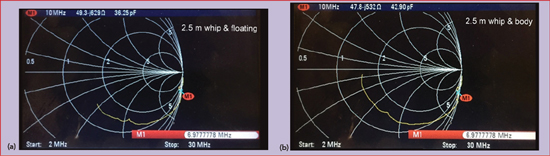
Figure 18 Measured S11 of a 2.5 m whip antenna with floating ground (a) and ground next to the body (b).
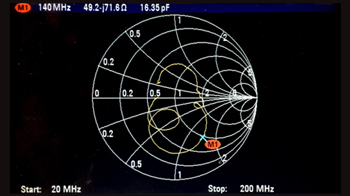
Figure 19 Measured S11 of an antenna for a VHF/UHF radio, from 20 to 200 MHz.
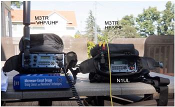
Figure 20 VHF/UHF (left) and HF/VHF (right) manpacks. The UHF/VHF manpack shown uses a thick vertical pole antenna, and the HF manpack uses a 5 m dipole (the yellow wire).
References
- U. L. Rohde, “Die Anpassung von Kurzen Stabantennen fur KW-Sender,” Funkschau 1974, Heft 7.
- U. L. Rohde, “Match Antenna Over 1.5 to 30 MHz Range with Only Two Adjustable Elements,” Electronic Design 19, September 13, 1975.
- L. Bergmann and H. Lassen, “Ausstrahlung, Ausbreitung und Aufnahme Elektromagnetischer Wellen,” Berlin, Verlag Von Julius Springer, 1940.
- A. Vlcek, H. Hartnagel and K. Mayer, “Zinke.Brunswig Hochfrequentztechnik 1 Hochfreqenzfilter, Leitungen, Antennen, 6th Edition,” Springer.
- W. E Sabin and E. O. Schoenike, “Single Sideband Systems and Circuits, 2nd Edition,” McGraw Hill, pp. 582–605.
- U. L. Rohde, M. Salazar-Palma and T. Sarkar, “Electrically Short Antennas,” www.synergymwave.com/articles/2016/Antenna_presentation.pdf.
- Chapters 22, “Antennas,” and Chapter 18, “The ARRL Handbook for Radio Communications 2013,” pp. 18.6.
- U. L. Rohde, “Theory of Intermodulation and Reciprocal Mixing: Practice, Definitions and Measurements in Devices and Systems, Part 1,” QEX, November/December 2002.
- U. L. Rohde, “Theory of Intermodulation and Reciprocal Mixing: Practice, Definitions and Measurements in Devices and Systems, Part 2,” QEX, January/February 2003.
- “Antenna (radio),” Wikipedia, en.wikipedia.org/wiki/Antenna.
- “Antenna Tuner,” Wikipedia, en.wikipedia.org/wiki/Antenna_tuner.
- U. L. Rohde, J. C. Whitaker and H. Zahnd, “Communications Receivers: Principles and Design, 4th Edition,” McGraw Hill, 2017.
- K. Siwiak and Y. Bahreini, “Radiowave Propagation and Antennas for Personal Communications, 3rd Edition,” Artech House, 2007, pp. 20–22.
- R. A. Sainati and D. E. Fessenden, “Performance of an Electrically Small Antenna Amplifier Circuit.”
- J. Taylor, S. Franke and W. Somerville, “Work the World with WSJT-X, Part 1,” QST, October 2017, pp. 30–36.
- J. Taylor, S. Franke and W. Somerville, “Work the World with WSJT-X, Part 2: Codes, Modes and Cooperative Software Development,” QST, November 2017, pp. 34–39.
- U. L. Rohde, “Receiver Measurements, How to Evaluate Receivers,” QEX, July/August 2005

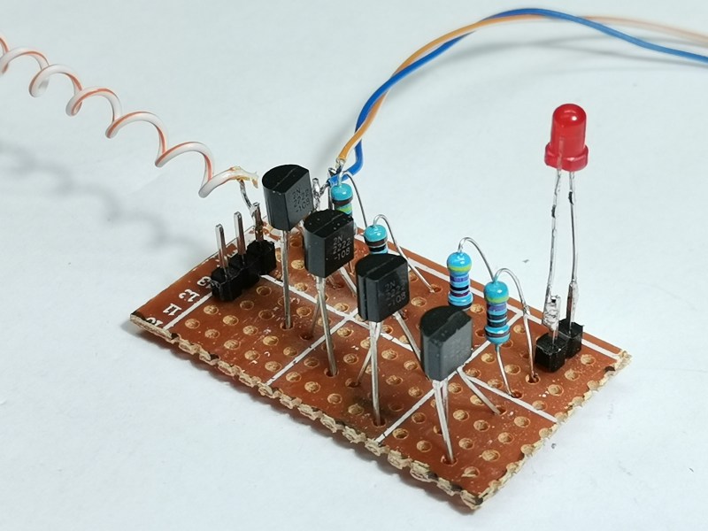
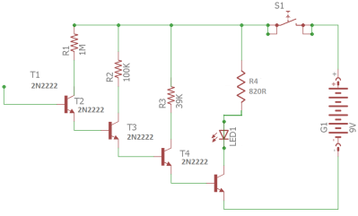 https://hackaday.io/project/183476-diy-simple-sensitive-emf-detector-and-electroscope ” data-image-caption=”” data-medium-file=”https://hackaday.com/wp-content/uploads/2022/01/2578171641635041412.png?w=400″ data-large-file=”https://hackaday.com/wp-content/uploads/2022/01/2578171641635041412.png?w=800″ width=”400″ height=”242″>
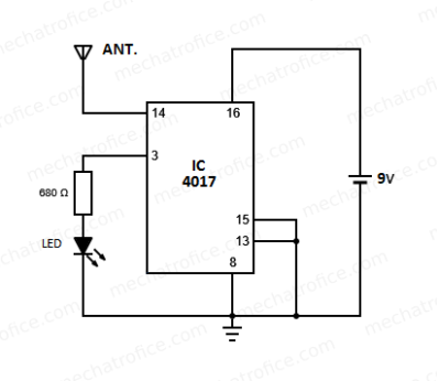 https://hackaday.io/project/183476-diy-simple-sensitive-emf-detector-and-electroscope ” data-image-caption=”” data-medium-file=”https://hackaday.com/wp-content/uploads/2022/01/7237471641635055278.png?w=400″ data-large-file=”https://hackaday.com/wp-content/uploads/2022/01/7237471641635055278.png?w=412″ width=”400″ height=”347″>

 Op 6 september 2021 zijn enkele overeenkomsten getekend waarmee de bestaande 70cm DMR-repeater PI1ZLB formeel is overgedragen aan de Stichting Radioamateurstations Zuid-Limburg. Hiermee is de continuïteit van deze repeater veiliggesteld.