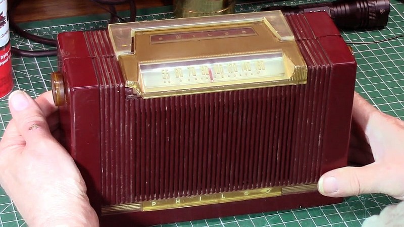
There are many ways to build a radio receiver, but most have a few things in common, such as oscillators, tuned circuits, detectors, mixers, and amplifiers. Put those together in the right order and you’ve got a receiver ready to tune in whatever you want to listen to. But if you don’t really care about tuning and want to hear everything all at once, that greatly simplifies the job and leaves you with something like this homebrew all-band receiver.
Granted, dispensing with everything but a detector and an audio amplifier will seriously limit any receiver’s capabilities. But that wasn’t really a design concern for [Ido Roseman], who was in search of a simple and unobtrusive way to monitor air traffic control conversations while flying. True, there are commercially available radios that tune the aviation bands, and there are plenty of software-defined radio (SDR) options, but air travel authorities and fellow travelers alike may take a dim view of an antenna sticking out of a pocket.
So [Ido] did a little digging and found a dead-simple circuit that can receive signals from the medium-wave bands up into the VHF range without regard for modulation. The basic circuit is a Schottky diode detector between an antenna and a high-gain audio amplifier driving high-impedance headphones; [Ido] built a variation that also has an LM386 amplifier stage to allow the use of regular earbuds, which along with a simple 3D-printed case aids in the receiver’s stealth.
With only a short piece of wire as an antenna, reception is limited to nearby powerful transmitters, but that makes it suitable for getting at least the pilot side of ATC conversations. It works surprisingly well — [Ido] included a few clips that are perfectly understandable, even if the receiver also captured things like cell phones chirping and what sounds like random sferics. It seems like a fun circuit to play with, although with our luck we’d probably not try to take it on a plane.
If there’s anything more annoying to an amateur radio operator than noise, we’re not sure what it could be. We’re talking about radio frequency noise, of course, the random broadband emissions that threaten to make it almost impossible to work the bands and pick out weak signals. This man-made interference is known as “QRM” in ham parlance, and it has become almost intolerable of late, as poorly engineered switch-mode power supplies have become more common.
But hams love a technical challenge, so when a nasty case of QRM raised its ugly head, [Kevin Loughlin (KB9RLW)] fought back. With an unacceptable noise floor of S8, he went on a search for the guilty party, and in the simplest way possible — he started flipping circuit breakers. Sure, he could have pulled out something fancier like a TinySA spectrum analyzer, but with his HF rig on and blasting white noise, it was far easier to just work through the circuits one by one to narrow the source down. His noise problem went away with the living room breaker, which led to pulling plugs one by one until he located the culprit: a Roomba vacuum’s charging station.
Yes, this is a simple trick, but one that’s worth remembering as at least a first pass when QRM problems creep up. It probably won’t help if the source is coming from a neighbor’s house, but it’s a least worth a shot before going to more involved steps. As for remediation, [Kevin] opts to just unplug the Roomba when he wants to work the bands, but if you find that something like an Ethernet cable is causing your QRM issue, you might have to try different measures.
Although ham radio can be an engaging, rewarding hobby, it does have a certain reputation for being popular among those who would fit in well at gated Florida communities where the preferred mode of transportation is the golf cart. For radio manufacturers this can be a boon, as this group tends to have a lot of money and not demand many new features in their technology. But for those of us who skew a bit younger, there are a few radios with custom firmware available that can add a lot of extra capabilities.
The new firmware is developed by [NicSure] for the Tidradio TD-H3 and TD-H8 models and also includes a browser-based utility for flashing it to the radio without having to install any other utilities. Once installed, users of these handheld radios will get extras like an improved S-meter and detection and display of CTCSS tones for repeater usage. There’s also a programmer available that allows the radio’s memory channels to be programmed easily from a computer and a remote terminal of sorts that allows the radio to be operated from the computer.
One of the latest firmware upgrades also includes a feature called Ultra Graph which is a live display of the activity on a selected frequency viewable on a computer screen. With a radio like this and its upgraded firmware, a lot of the capabilities of radios that sell for hundreds of dollars more can be used on a much more inexpensive handheld. All of this is possible thanks to an on-board USB-C interface which is another feature surprisingly resisted by other manufacturers even just for charging the batteries.
Analog radio broadcasts are pretty simple, right? Tune into a given frequency on the AM or FM bands, and what you hear is what you get. Or at least, that used to be the way, before smart engineers started figuring out all kinds of sneaky ways for extra signals to hop on to mainstream broadcasts.
Subcarrier radio once felt like the secret backchannel of the airwaves. Long before Wi-Fi, streaming, and digital multiplexing, these hidden signals beamed anything from elevator music and stock tickers to specialized content for medical professionals. Tuning into your favorite FM stations, you’d never notice them—unless you had the right hardware and a bit of know-how.
Sub-what now?
Subcarrier radio was approved by the FCC under the Subsidiary Communications Authorization. This allowed both AM and FM radio stations to deliver additional content through subchannel broadcasting on their existing designated frequency. Practicalities mean that only FM stations could reasonably use this technique to broadcast additional audio content; AM radio stations were too limited in bandwidth to do so. In the latter case, only low-bitrate data could be sent on a subcarrier. 1983 saw the deregulation of subcarrier broadcasts, with existing broadcasters able to use them largely as they wished.
To understand how this let FM radios broadcast extra programming, we need to know how subcarriers work. Basically, in this context, a subcarrier is a high-frequency signal outside the range of human hearing—usually something like a sine wave at a frequency of 20 KHz to 100 KHz or so. This signal is then amplitude modulated with the desired secondary audio program for broadcast. As this signal is beyond the range of human hearing, it can be mixed with the regular station’s main audio feed without perceptibly altering it to any great degree. The mixed signal is then frequency modulated on to the radio station’s main carrier signal (usually in the range of 88-108 MHz) and sent up the tower for broadcast over radio.
Modern FM stereo transmissions have lots of stuff multiplexed on to them. There’s plenty of bandwidth to fit in a number of signals—including stereo data at 38 kHz, and subcarrier audio transmissions at 67 kHZ or 92 kHz. Microsoft also tried sending data over subchannels with Directband, but it didn’t catch on. Credit: modified, public domain
For subchannel broadcasting, FM stations typically used subcarriers at 67 kHz or 92 kHz to carry additional low-fidelity mono audio feeds. These carrier frequencies were chosen to avoid the existing subcarrier signal in FM stereo broadcasts, which carried a left-right channel difference signal at 38 kHz.
Subcarriers were a neat little lifehack that let a single frequency do double or triple duty. A single FM station could deliver its main program, plus a bonus low-fidelity mono channel for various purposes. This facility was used for all kinds of obscure uses. Some broadcasters delivered background music for piping into department stores and the like, while others created special channels reserved for reading-for-the-blind organizations.
The Physician’s Radio Network was also a notable user, which broadcast information of specific relevance to medical professionals. However, the limited audience made it a difficult prospect to keep running from a commercial standpoint, even though it saved money by merely rebroadcasting one hour of programming around the clock on any given day. It eventually went off the air in 1981.
Tuning into these broadcasts wasn’t possible on a regular FM radio. Instead, you needed a device specifically built to pull the subcarrier signal out of the radio broadcast and then demodulate it back into listenable audio. By and large, organizations broadcasting on subchannels would distribute special radios that were tuned to only decode their sub-carrier station. The hardware involved wasn’t complex—it just involved demodulating the FM broadcast signal, then filtering out the subcarrier signal and demodulating that back into audio.
Microsoft used subcarriers to broadcast data to coffee machines and smartwatches in the early 2000s. Credit: Zuzu, CC BY-SA 3.0
FM subcarriers weren’t just for audio, either. Microsoft famously used 67.7 kHz subcarriers on FM radio stations for its now-defunct DirectBand datacast network. It could deliver data at 12 kbit/second, or over 100 MB a day. The technology was used to deliver things like weather reports and stock prices to early smartwatches and coffee makers in the days before WiFi and celluar internet were cheap and everywhere.
From a hardware hacker’s perspective, these channels were a fun challenge to hunt down. With the right radio receiver and a bit of circuit hacking to tap off the baseband signal, you could decode the subcarrier and reveal the hidden broadcast. Some hobbyists rigged up surplus SCA receivers—often stuff found at flea markets or hamfests—to get free background music, weather reports, or any niche audio that happened to be riding along. Alternatively, decoding the subcarrier was entirely possible by building your own gear. It was kind of a neat analog puzzle—filter out the main audio, isolate the frequency where the secret channel lived, and then demodulate it. The hardware you’d use looked suspiciously like the guts of a standard FM radio, just with a few added filters and demodulation stages stuck in. These days, software defined radio techniques make doing the same thing comparatively easy.
Though it felt like eavesdropping, this wasn’t exactly some top-secret espionage. While technically unauthorized reception was frowned upon by the FCC, it wasn’t heavily policed. Subcarrier channels didn’t exactly have roving gangs of enforcers prowling about the neighborhood. Mostly, these subcarriers delivered paid subscription services, like Muzak, or nonprofit programming authorized under the station’s broadcast license. Their decline coincided with the rise of digital technologies and more flexible content-delivery methods. By the late 20th century, satellite feeds, internet streaming, and multicast digital channels rendered analog subcarriers quaint and unnecessary.
Still, SCA subcarrier signals remain a fascinating piece of broadcasting history. A few still linger today, but it’s now a more obscure medium than ever, lost as mainstream technology has moved on. It’s a reminder that even in the old days of broadcast radio, clever engineers found ways to pack more data into the same old bandwidth—long before we started streaming everything in sight.
If you were in Tunisia in October, you might have caught some of the Morse Code championships this year. If you didn’t make it, you could catch the BBC’s documentary about the event, and you might be surprised at some of the details. For example, you probably think sending and receiving Morse code is only for the elderly. Yet the defending champion is 13 years old.
Teams from around the world participated. There was stiff competition from Russia, Japan, Kuwait, and Romania. However, for some reason, Belarus wins “almost every time.” Many Eastern European countries have children’s clubs that teach code. Russia and Belarus have government-sponsored teams.
Morse code is very useful to amateur radio operators because it allows them to travel vast distances using little power and simple equipment. Morse code can also assist people who otherwise might have problems communicating, and some assistive devices use code, including a Morse code-to-speech ring the podcast covers.
The speed records are amazing and a young man named [Ianis] set a new record of 1,126 marks per minute. Code speed is a little tricky since things like the gap size and what you consider a word or character matter, but that’s still a staggering speed, which we estimate to be about 255 words per minute. While we can copy code just fine, at these speeds, it sounds more like modem noises.
For the amateur radio operator with that on-the-go lifestyle, nothing is more important than having your gear as light and packable as possible. If you’re lugging even a modest setup out into the woods, every ounce counts, which is why we love projects like this packable dipole antenna feedpoint.
At its simplest, a dipole antenna is just two pieces of wire cut to a specific, frequency-dependent length connected to a feedline. In practical terms, though, complications arise, such as keeping common-mode currents off the feedline and providing sturdy mechanical support for the antenna to suspend it safely. [Ham Radio Dude]’s design handles both those requirements while staying as small and packable as possible. The design starts with a bifilar 1:1 current balun, which is wound on an FT82-43 ferrite toroid with 22 AWG magnet wire. One side of the balun is connected to a BNC connector while the other is connected to a pair of Wago splice connectors that are glued together. A loop of paracord for mechanical strain relief is added, and the whole thing gets covered in heat-shrink tubing. The antenna is deployed by attaching a feedline to the BNC, clipping quarter-wave wires into the Wago terminals, and hoisting the whole thing aloft. Full build details are in the video below.
People will no doubt be quick to point out that these Wago terminals are rated for a minimum of 18 AWG wire, making them inappropriate for use with fine magnet wire. True enough, but [Dude] was able to get continuity through the Wagos, so the minimum gauge is probably more of an electrical code thing. Still, you’ll want to be careful that the connections stay solid, and it might pay to look at alternatives to the Wago brand, too.
The web browser started life as a relatively simple hypertext reading application, but over the 30+ years since the first one displayed a simple CERN web page it has been extended to become the universal platform. It’s now powerful enough to run demanding applications, for example a full software-defined radio. [Jtarrio] proves this, with an application to use an RTL-SDR, in HTML5.
It’s a fork of a previous Google-Chrome-only FM receiver, using the HTML5 WebUSB API, and converted to TypeScript. You can try it out for yourself if you have a handy RTL dongle lying around, it provides an interface similar to the RTL apps you may be used to.
The Realtek digital TV chipset has been used as an SDR for well over a decade now, so we’re guessing most of you with an interest in radio will have one somewhere. The cheap ones are noisy and full of spurious peaks, but even so, they’re a bucket of fun. Now all that’s needed is the transmit equivalent using a cheap VGA adapter, and the whole radio equation could move into the browser.
At the time of its construction in the 1950s, the Dwingeloo Radio Observatory was the largest rotatable telescope in the world with a dish diameter of 25 meters. It was quickly overtaken in the rankings but was used by astronomers for decades until it slowly fell into disuse in the early 2000s. After a restoration project the telescope is now a national heritage site in the Netherlands where it is also available for use by radio amateurs. Recently this group was able to receive signals from Voyager 1.
Famously, Voyager 1 is the furthest manmade object from Earth, having been launched on a trajectory out of the solar system in 1977. As a result of distance and age, the signals it sends out are incredibly faint. The team first had to mount a new antenna to the dish, which was not originally designed for signals in this frequency which added to the challenge. They then needed to use orbital predictions of the spacecraft in order to target the telescope and also make the correct adjustments to the received signal given that there is significant Doppler shift now as well. But with that all out of the way, the team was successfully able to receive the Voyager 1 signal on this telescope.
Only a few telescopes in the world have ever been able to accomplish this feat, making it all the more impressive. Normally Voyager 1 is received using the Deep Space Network, a fleet of much larger dishes stationed around the world and designed for these frequencies. But this team is used to taking on unique challenges. They also decoded the first ham radio station on the moon and made a radar image of the moon using LoRa.
Oscillators may use crystals as precise tuned circuits. If you have a vector network analyzer (VNA) — or even some basic test equipment — you can use it to learn the parameters of a crystal. [All Electronics Channel] has the details, and you can see how in the video below.
There was a time when a VNA was an exotic piece of gear, but these days they are relatively common. Crystal parameters are important because crystals have a series resonance and a parallel resonance and they are not at the same frequency. You also may need to know how much loading capacitance you have to supply to get the crystal at the right frequency.
Sometimes, you want to pull the crystal frequency, and the parameters will help you figure that out, too. It can also help if you have a crystal specified as series in a parallel-mode oscillator or vice versa.
If you don’t have a VNA, you can use a tracking signal generator, as [Grégory] shows towards the middle of the video. The quality of a tuned circuit depends on the Q factor, and crystals have a very high Q factor.
If you want to analyze an antenna, you can use simulation software or you can build an antenna and make measurements. [All Electroncs Channel] does both and show you how you can do it, too, in the video below.
The antenna in question is a loop antenna. He uses a professional VNA (Vector Network Analyzer) but you could get away with a hobby-grade VNA, too. The software for simulation is 4NEC2.
The VNA shows the electrical characteristics of the antenna, which is one of the things you can pull from the simulation software. You can also get a lot of other information. You’d need to use a field strength meter or something similar to get some of the other information in the real world.
The antenna simulation software is a powerful engine and 4NEC2 gives you an easy way to use it with a GUI. You can see all the graphs and plots easily, too. Unfortunately, it is Windows software, but we hear it will run under Wine.
The practical measurement is a little different from the simulation, often because the simulation is perfect and the real antenna has non-ideal elements. [Grégory] points out that changing simulation parameters is a great way to develop intuition about — in this case — antennas.