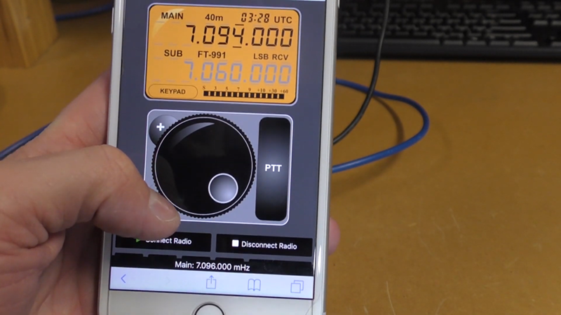
One problem with ham radio these days is that most hams live where you can’t put a big old antenna up due to city laws and homeowner covenants. If you’re just working local stations on VHF or UHF, that might not be a big problem. But for HF usage, using a low profile antenna is a big deal. However, most modern radios can operate remotely. Well-known ham radio company MFJ now has the RigPi Station Server and [Ham Radio DX] has an early version and did a review.
As the name implies, the box contains a Raspberry Pi. There’s also an audio interface. The idea is to consolidate rig control along with other station control (such as rotators) along with feeding audio back and forth to the radio. It also sends Morse code keying to the radio. The idea is that this box will put your radio on the network so that you operate it using a web browser on a PC or a mobile device.
According to MFJ, you can operate voice, Morse code, or digital modes easily and remotely. The box uses open source software that can control over 200 different radios and 30 rotors. Of course, you could build all this yourself and use the same open source software, but it is nicely packaged. [Ham Radio DX] says you don’t need to know much about the Pi or Linux to use the box, although clearly you can get into Linux and use the normal applications if you’re so inclined.
Even if you don’t want to transmit, we could see a set up like this being used for remote monitoring. We’d like to see a companion box for the remote end that had the audio hardware, a keyer, and perhaps a knob to act as a remote control of sorts. Of course, you could probably figure out how to do that yourself. We wonder if some ham clubs might start offering a remote radio via an interface like this — we’ve seen it done before, but not well.
Your $50 radio probably isn’t going to work with this, and if you use FT8, you could argue you don’t need to be there anyway.
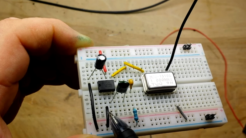
When you start watching [learnelectronic’s] two-part series about making a radio transmitter, you might not agree with some of his history lessons. After all, the origin of radio is a pretty controversial topic. Luckily, you don’t need to know who invented radio to enjoy it.
The first transmitter uses a canned oscillator, to which it applies AM modulation. Of course, those oscillators are usually not optimized for that service, but it sort of works. In part two he reduces the frequency to 1 MHz at which point it can be listened to on a standard AM radio, before adding an amplifier so any audio source can modulate the oscillator. There’s a lot of noise, but the audio is clearly there.
This is far from practical of course, but combined with a crystal radio it could make an awesome weekend project for a kid you want to hook on electronics. The idea that a few simple parts could send and receive audio is a pretty powerful thing. If you get ready to graduate to a better design, we have our collection.
Humanity had barely taken its first tentative steps into space with primitive satellites when amateur radio operators began planning their first satellites. Barely four years after Sputnik’s brief but momentous launch and against all odds, OSCAR 1 was launched as a secondary payload from an Air Force missile taking a spy satellite into orbit. Like Sputnik, OSCAR 1 didn’t do much, but it was a beginning.
Since then, amateur radio has maintained a more or less continuous presence in space. That first OSCAR has been followed by 103 more, and hams have flown on dozens of missions from the Space Shuttle to the ISS, where pretty much everyone is a licensed amateur. And now, as humans prepare once again to journey into deep space via the stepping stone of the proposed Lunar Gateway, amateur radio is planning on going along for the ride.
A Gateway to Deep Space
More properly known at the Lunar Orbital Platform-Gateway or LOP-G, the Lunar Gateway is intended to be a way-station between the Earth and the Moon, and thence to the deeper parts of the solar system and beyond. Like the ISS, the Gateway will consist of multiple modules serving specific purposes, all docked together into a space station that will serve as a staging area for both crewed and robotic missions. The Gateway will also be a collaborative station, with corporations and agencies from multiple nations contributing hardware
Unlike the ISS, though, the Gateway will be fairly limited in size and therefore in the scope of missions it will host. Although it will have room to accommodate small crews for up to three months at a time, there is no intention to keep the Gateway permanently crewed like the ISS is. The Gateway will serve mainly as a cosmic rest stop, a place where astronauts and hardware can meet up before the final push to the moon.
The Gateway has met with a fair amount of criticism from a wide range of commentators, from former astronauts to space agency administrators to journalists and academicians. Most of the criticism seems to be based on the feeling that humanity’s push back into deep space is not nearly bold enough, and that instead of going on a “been there, done that” mission to the Moon, we should instead just head to Mars. And those who feel that returning to the Moon is a valid goal seem to think that a space station waypoint would just be an unnecessary expense that would hinder investment in the technologies needed for a direct-to-Moon mission.
But as is often the case, all of this criticism is trumped by the realities of orbital mechanics. As Brian Benchoff recently explained, the Lunar Gateway opens up nearly the entire surface of the Moon to our exploration, including the interesting bits near the poles that hold all the water. Without the Lunar Gateway and it’s extremely weird orbit – more on that in a second – all we would have access to on the Moon is basically the same mid-latitude areas pretty much every mission has visited for the last sixty years. Sure, we could land a mission at the equator and take a MoonMobile to the poles, but that seems pretty foolish – why drive when you can fly?
Weird for a Reason
A little detail about the weird orbit the Lunar Gateway will use is in order, as it will tie into the ham aspect of all this. As Brian pointed out, the orbit is referred to as a “near-rectilinear halo orbit”, or NRHO. A glance at the orbital path shown most often in media packs and other supporting information for the Lunar Gateway appears to show the space station in a polar orbit around the Moon, but with occasional mid-orbit reversals, seemingly in opposition to the laws of physics. What exactly is going on here?
To understand the NRHO and how it will affect Lunar Gateway operations, including amateur radio access, you got to look at the orbit from another angle. All those loopy looking animations mentioned before represent the orbit when viewed from a Moon-centered inertial frame. That makes the Lunar Gateway appear to regularly move retrograde, in much the same way that the combined orbits of Earth and Mars make the Red Planet seem to move “backward” in the night sky. The NRHO from the Moon’s frame of reference can be seen in the bottom right of the video below.
However, when looked at from an Earth-centered frame of reference, the NRHO starts to make more sense. The Lunar Gateway is actually in orbit around the Earth, or more correctly, around the Earth-Moon L2 Lagrange Point. The Lunar Gateway will be in a constant game of follow-the-leader with the Moon, catching up with it every week or so only to flung back down below the orbital plane to repeat the cycle.
Decisions, Decisions
The unusual orbit the Lunar Gateway will follow is inherently unstable, and will require the occasional boost to maintain it. NASA has specified ion thrusters for station-keeping, which contribute to the need for 60 kilowatts of solar power. This should mean that whatever ham gear makes it aboard the first module of the station, the Power and Propulsion Element, or PPE, will not have to compete for power, at least initially.
So what gear is actually going to make it to the Gateway? For now, that’s mostly an open question. Planning for the ham station aboard the Gateway is the job of AMSAT, the Radio Amateur Satellite Corporation, which is the outfit behind the OSCAR satellites. They’ve formed a working group called AREx, or Amateur Radio Exploration, which has been meeting twice a month to decide which bands and modes will be supported; this in turn will help define the equipment needed.
Whatever gear ends up flying, we can assume that making contact with the Gateway will be at least moderately challenging. For comparison, contacting the hams aboard the ISS is fairly easy, needing little more than a simple homebrew antenna and a mobile transceiver or even a decent handheld. On the other end of the scale, it’s tempting to assume that since the Lunar Gateway will be most of the way to the Moon, making contact will be about as difficult as Earth-Moon-Earth, or EME, contacts. EME is uber-ham stuff, often using huge, steerable antennas and powerful transmitters to blast the Moon with signals so that a weak echo will come back down for another ham to receive. The path loss for EME is on the order of 250 dB or more depending on frequency, and the technical challenges of digging a signal out of the galactic noise are significant.
Luckily, hams won’t be relying on passive reflections from the Moon’s surface to make contacts, so contacts should be easier. Chances are good that a tracking antenna will still be needed, but the antenna required will probably be far more modest than some of the elaborate EME antennas in use today. The 2-meter band (144-146 MHz) is often used for EME, so it’s quite likely that it’ll be used for the Lunar Gateway too. We can also guess that weak-signal digital modes like JT65, with its powerful error correction, will be supported. Also, since the Lunar Gateway will not be permanently crewed, chances are good that some automatic stations will be up there, perhaps a packet digipeater, or digital repeater, like the ISS has.
Almost all of the details of the amateur radio presence on the Lunar Gateway remain to be seen, but given how early in the design process hams were looped in, the design of the spacecraft, its orbital dynamics, and the proven record of ham radio in near-space, chances are excellent that hams be able to talk to someone in deep space within the next five years or so.
Before swearing my fealty to the Jolly Wrencher, I wrote for several other sites, creating more or less the same sort of content I do now. In fact, the topical overlap was enough that occasionally those articles would get picked up here on Hackaday. One of those articles, which graced the pages of this site a little more than seven years ago, was Getting Started with RTL-SDR. The original linked article has long since disappeared, and the site it was hosted on is now apparently dedicated to Nintendo games, but you can probably get the gist of what it was about from the title alone.
An “Old School” RTL-SDR Receiver
When I wrote that article in 2012, the RTL-SDR project and its community were still in their infancy. It took some real digging to find out which TV tuners based on the Realtek RTL2832U were supported, what adapters you needed to connect more capable antennas, and how to compile all the software necessary to get them listening outside of their advertised frequency range. It wasn’t exactly the most user-friendly experience, and when it was all said and done, you were left largely to your own devices. If you didn’t know how to create your own receivers in GNU Radio, there wasn’t a whole lot you could do other than eavesdrop on hams or tune into local FM broadcasts.
Nearly a decade later, things have changed dramatically. The RTL-SDR hardware and software has itself improved enormously, but perhaps more importantly, the success of the project has kicked off something of a revolution in the software defined radio (SDR) world. Prior to 2012, SDRs were certainly not unobtainable, but they were considerably more expensive. Back then, the most comparable device on the market would have been the FUNcube dongle, a nearly $200 USD receiver that was actually designed for receiving data from CubeSats. Anything cheaper than that was likely to be a kit, and often operated within a narrower range of frequencies.
Today, we would argue that an RTL-SDR receiver is a must-have tool. For the cost of a cheap set of screwdrivers, you can gain access to a world that not so long ago would have been all but hidden to the amateur hacker. Let’s take a closer look at a few obvious ways that everyone’s favorite low-cost SDR has helped free the RF hacking genie from its bottle in the last few years.
Hardware Evolution
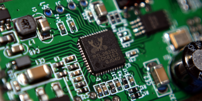
Even though the project is called RTL-SDR, the Realtek RTL2832U chip is in reality just half of the equation; it’s a USB demodulator chip that needs to be paired with a tuner to function. In the early days, there were a number of different tuners in use, and figuring out which one you were getting was a pretty big deal. The Elonics E4000 was the most desirable tuner as it had the widest frequency range, but it could be difficult to know ahead of time what you were getting.
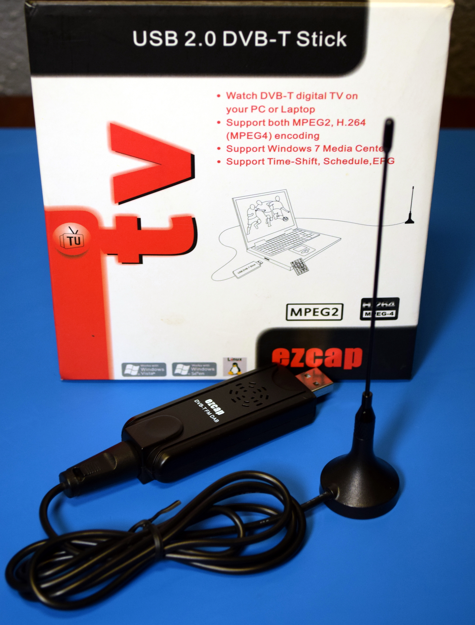
The packaging and documentation were all but useless; either the manufacturer didn’t bother to include the information, or if they did, it would often become outdated as new revisions of the product were produced. The only way to be sure about what you were getting was to see if somebody had already purchased that particular model and reported on their findings. Luckily, the tuners were cheap enough that you could buy a couple and experiment. In those days, it wasn’t uncommon to find RTL-SDR compatible devices for less than $10 from import sites.
Opening up a contemporary RTL2832U+E4000 receiver, we can see they were relatively simple affairs. The flimsy plastic case doesn’t do much to prevent interference, and the Belling-Lee connector connector is intended for use with a traditional TV antenna. Note this particular model features an IR receiver so the user could change TV channels with the included remote; a reminder of what this device was actually built for.
These days, you don’t need to wade through pages of nearly identical looking USB TV tuners to find compatible hardware. There are now several RTL2832U-based receivers which are specifically designed for RTL-SDR use, generally selling for around $30. These devices not only address the shortcomings of the original hardware offerings, but in many cases add in new capabilities that simply wouldn’t have made sense to include back when they were just for watching TV on your computer.
Here we have the “RTL-SDR Blog v3” receiver, which is one of the most popular “next generation” RTL-SDR receivers. The plastic case has been replaced with an aluminum one that not only reduces interference, but helps the board dissipate heat while in operation. The crystal has been upgraded to a temperature compensated oscillator (TCXO) which helps reduce temperature drift. The R820T2 tuner is paired with a standard SMA antenna connector, and both it and the RTL2832U have some unused pins broken out if you’re looking to get into developing modifications or expansions to the core hardware.
Software Library
The improvements to the base RTL-SDR hardware are welcome, and it’s nice to not have to worry about whether or not the receiver you’ve purchased is actually going to work with the drivers, but realistically those changes mainly benefit the more hardcore users who are pushing the edge of the envelope. If you’re just looking to sniff some 433 MHz thermometers, you don’t exactly need a TCXO. For most users, the biggest improvements have come in the software side of things.
For one, the RTL-SDR package is almost certainly going to be in the repository of your favorite GNU/Linux distribution. Unless you need some bleeding edge feature, you won’t have to compile the driver and userland tools from source anymore. The same will generally be true for the SDR graphical frontend, namely gqrx by Alexandru Csete. Those two packages are enough to get you on the air and browsing for interesting signals, but that’s just the beginning. The rise of cheap SDRs has inspired a number of fantastic new software packages that are light-years ahead of what was available previously.
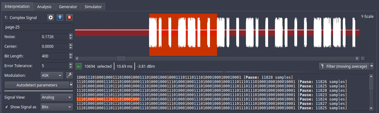
Certainly one of the best examples is Universal Radio Hacker, an all-in-one tool that lets you search for, capture, and ultimately decode wireless signals. Whether it’s a known protocol for which it already has a built-in decoder, or something entirely new that you need to reverse engineer, Universal Radio Hacker is a powerful tool for literally pulling binary data out of thin air. Those looking to reverse unknown wireless protocols should also take a look at inspectrum, another tool developed in the last few years that can be used to analyze captured waveforms.
Decoding a captured ASK OOK signal in Universal Radio Hacker
If you’re more interested in the practical application of these radios, there have also been a number of very impressive “turn-key” applications developed that leverage the high availability of low-cost SDRs. One such project is dump1090, a ADS-B decoder that was specifically developed for use with the RTL-SDR. With a distributed network of receivers, the software has allowed the community to democratize flight tracking through the creation of open data aircraft databases.
The Gift of Inspiration
In the years since its inception, the RTL-SDR project has become the de facto “first step” for anyone looking to experiment with radio. It’s cheap, it’s easy, and since the hardware is incapable of transmission, you don’t have to worry about accidentally running afoul of the FCC or your local equivalent. Honestly, it’s difficult to think of a valid reason not to add one of these little USB receivers to your bag of tricks; even if you only use it once, it will more than pay for itself.
Ultimately, this is the greatest achievement of the RTL-SDR project. It drove the entry barrier for radio experimentation and hacking so low that it’s spawned a whole new era. From the unique vantage point offered by Hackaday, we can see the sharp uptick of RF projects that correspond to the introduction of an easy to use and extremely affordable software defined radio. People who might never have owned a “real” radio beyond the one in their car can now peel back the layers of obscurity that in the past kept the vast majority of us off the airwaves. This is a very exciting time for wireless hacking, and things are only going to get more interesting from here on out. Long live RTL-SDR!
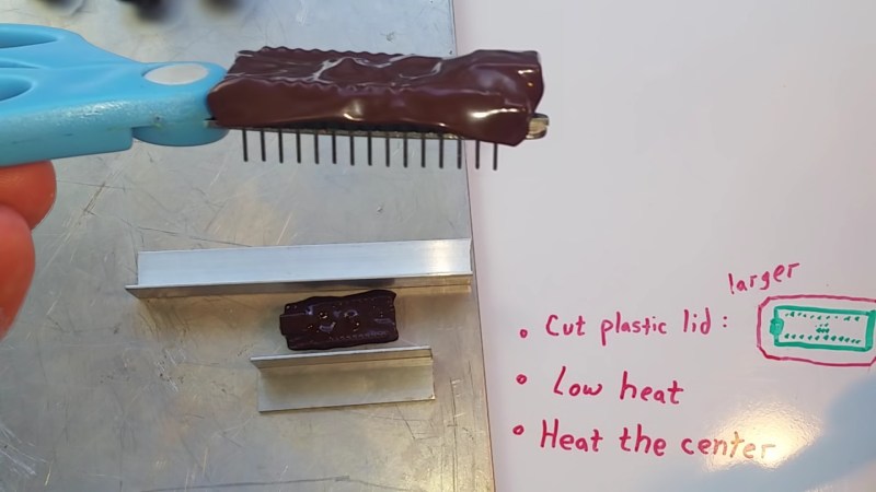
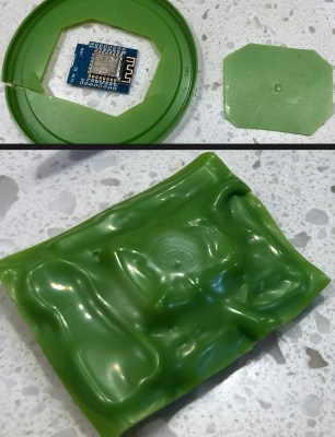
An errant wire snipping across the wrong electrical pins spells the release of your magic smoke. Even if you are lucky, stray parts are the root of boundless malfunctions from disruptive to deadly. [TheRainHarvester] shares his trick for covering an Arduino Nano with some scrap plastic most of us have sitting in the recycling bin. The video is also after the break. He calls this potting, but we would argue it is a custom-made cover.
The hack is to cut a bit of plastic from food container lids, often HDPE or plastic #2. Trim a piece of it a tad larger than your unprotected board, and find a way to hold it in place so you can blast it with a heat gun. When we try this at one of our Hackaday remote labs and apply a dab of hot glue between the board and some green plastic it works well. The video suggests a metal jig which would be logical when making more than one. YouTube commenter and tip submitter [Keith o] suggests a vacuum former for a tighter fit, and we wouldn’t mind seeing custom window cutouts for access to critical board segments such as DIP switches or trimmers.
We understand why shorted wires are a problem, especially when you daisy-chain three power supplies as happened in one of [TheRainHarvester]’s previous videos.
Hundreds of years from now, the story of humanity’s inevitable spread across the solar system will be a collection of engineering problems solved, some probably in heroic fashion. We’ve already tackled a lot of these problems in our first furtive steps into the wider galaxy. Our engineering solutions have taken humans to the Moon and back, but that’s as far as we’ve been able to send our fragile and precious selves.
While we figure out how to solve the problems keeping us trapped in the Earth-Moon system, we’ve sent fleets of robotic emissaries to do our exploration by proxy, to make the observations we need to frame the next set of engineering problems to be solved. But as we reach further out into the solar system and beyond, our exploration capabilities are increasingly suffering from communications bottlenecks that restrict how much data we can ship back to Earth.
We need to find a way to send vast amounts of data back as quickly as possible using as few resources as possible on both ends of the communications link. Doing so may mean turning away from traditional radio communications and going way, way up the dial and developing practical means for communicating with X-rays.
The Tyranny of Physics
The essential problems with deep space communications come from two sources – the inverse-square law and information theory. The inverse-square law states that the amount of energy at the receiving end of a radio communications link is inversely proportional to the square of the distance to the transmitter. Basically, radio waves spread out from the source and at very great distances tend to diminish into the background noise. That’s why deep-space communications networks tend to have large antennas on both ends of the link, to gather and focus as much of the weak signal as possible, as well as to be able to transmit a powerful and narrowly focused beam.
Information theory tells us that more data can be packed into higher frequency signals than lower frequencies. Early satellites didn’t need much bandwidth to do their jobs, so VHF and UHF radios were generally sufficient. But as spacecraft became more sophisticated and the amount of data they needed to send back increased, their communications links began shifting gradually up the electromagnetic spectrum into the microwave region. The Voyager probes, currently in interstellar space, have an uplink using 2.1 GHz for the relatively low-bandwidth tasks of vehicle control, with a downlink at 8.1 GHz, reflecting the increased bandwidth needed to send scientific data back to Earth.
For as stunning an engineering achievement as Voyager has been, and notwithstanding the fact that it’s still working more than 40 years after launch, its radio gear only barely supports its interstellar mission. To be fair, Voyager was never meant to last this long, and every bit of data that makes it back to Earth is just icing on the cake. But for future missions specifically designed for interstellar space, sending back enough data to make such missions feasible will require more bandwidth.
Small, Bright, and Fast
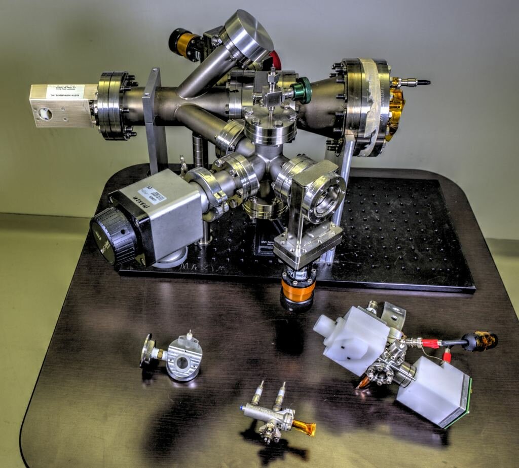
The Modulated X-Ray Source experiment. The miniature source is center bottom. Source: NASA/W. Hrybyk
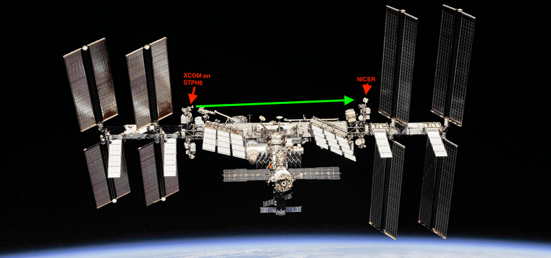
In late April, NASA is sending a pallet of gear up to the ISS, and one of the experiments stashed in the cargo is meant to explore the potential for X-ray communications, or XCOM, for deep space. The Modulated X-Ray Source (MXS) is a compact X-ray transmitter that will be mounted outside the space station. The receiver for this experiment is already installed; the Neutron Star Interior Composition Explorer (NICER) has been gathering X-ray spectra from neutron stars since 2017, while also gathering data about the potential for using X-ray pulsars as navigational beacons in a sort of “Galactic Positioning System”.
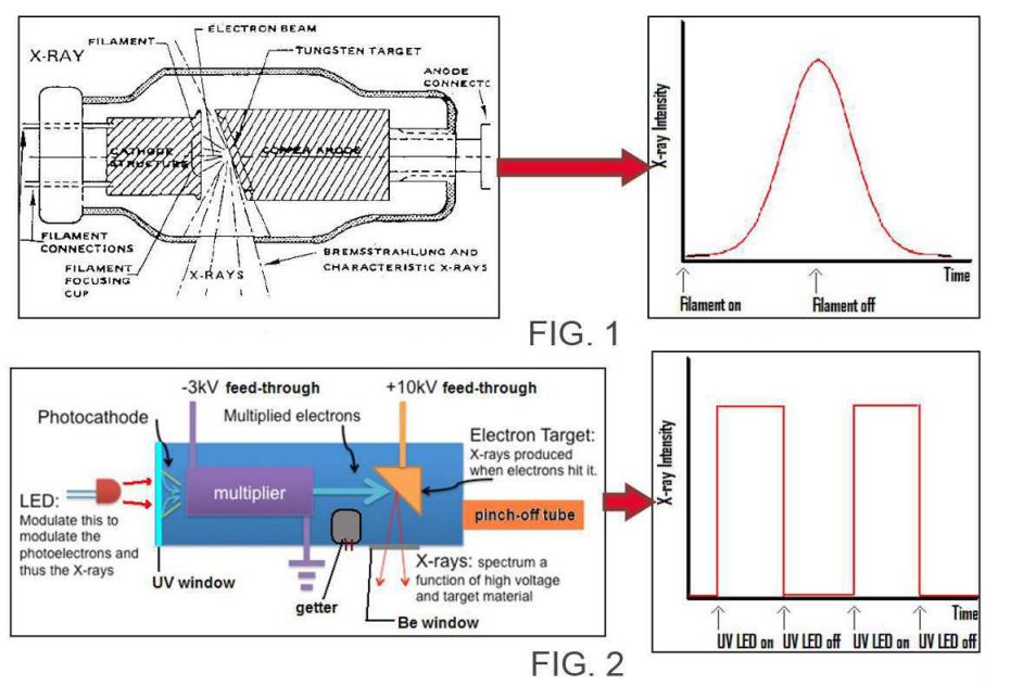
MXS is an interesting instrument. When one thinks of making X-rays, the natural tendency is to assume a traditional hot-cathode vacuum tube, where electrons are boiled off a filament and accelerated by an electric field in the range of 100 kilovolts to slam into a tungsten anode, would be used. But vacuum tubes like those found in a hospital X-ray suite aren’t the best space travelers, and even when ruggedized they’re too bulky and heavy to send upstairs.
So NASA researchers developed a more spaceflight-friendly X-ray generator. Rather than heating a filament to generate electrons, the X-ray source in MXS uses creates photoelectrons by bombarding a magnesium photocathode with UV light from LEDs. The few photoelectrons produced then enter an electron amplifier, an off-the-shelf component found in mass spectrometers that uses specially shaped chambers coated with a thin layer of semiconducting material. Each incident electron liberates a few secondary photoelectrons, which bounce off the other wall of the multiplier to create more electrons, greatly amplifying the signal. The huge stream of electrons is then accelerated by a 10 kV field to collide with the target anode and produce X-rays.
Comparison of hot-cathode X-ray tube to MXS. Source: NASA
While the MXS source sounds similar to a hot-cathode tube, there are important differences. First, the source can be made cheaply from off-the-shelf components and a 3D-printed metal enclosure. The whole assembly weighs only about 160 grams, fits in the palm of a hand, and has no unusual power or temperature control requirements. The big difference, though, is with how fast the X-rays can be turned on and off. A glowing filament can only heat up and cool down so quickly, meaning that effective modulation of X-ray from hot-cathode sources is difficult. In the MXS, X-rays are produced only when the UV LEDs are on, and those can be switching very quickly, in the sub-nanosecond range. The ability to modulate an X-ray beam lead to data rates in the gigabits per second range, greatly enhancing our ability to move data around in space.
What’s more, X-rays can be more tightly collimated than radio waves or even light, which is also being experimented with for space communications. The tighter X-ray beam spreads out less, making transmission more power efficient and reception easier by virtue of the strong signal from relatively bright transmitters.
Although the distance between the MXS and NICER in these XCOM experiments is only about 50 meters, they stand to position us for much better bandwidth for deep space communications. The MXS source itself has a lot of potential applications beyond XCOM too, from cheap, lightweight, low-power medical imaging on Earth and in space, navigational beacons for spacecraft, and even advanced chemical analysis by X-ray spectroscopy
We’ve seen lots of hacks about capturing weather images from the satellites whizzing over our heads, but this nicely written how-to from [Eric Sorensen] takes a different approach. Rather than capturing images from polar satellites that pass overhead a few times a day, this article looks at capturing images from GOES-17, a geostationary satellite that looks down on the Pacific Ocean. The fact that it is a geostationary satellite means that it captures the same view all the time, so you can capture awesome time-lapse videos of the weather.
The fact that GOES-17 is a geostationary satellite means that it is a bit more involved. While polar satellites that orbit at an altitude of 800km or so can be received with a random piece of wire, the 35,800 km altitude of geostationary satellites means that you need a better antenna. That doesn’t have to be that expensive, though: [Eric] used a $100 parabolic antenna and a $100 Airspy Mini SDR receiver connected to an Ubuntu laptop running some open source software to receive and decode the 1.7GHz signal of the satellite.
The other trick is to figure out where to point the dish. Because it is a geostationary satellite, this part has to be done carefully, as the parabolic antenna has only a small receiving angle. [Eric] designed a 3D-printed mount that fits onto a tripod for his antenna.
Capturing satellite weather images is a fascinating thing to do, and this adds another level of interest, as the images show the full disc of the earth. Capture a series over time, and you can see storms spin around and across the ocean, and see just how complicated they are.
This is an exciting day for me — we finally get to build some ham radio gear! To me, building gear is the big attraction of amateur radio as a hobby. Sure, it’s cool to buy a radio, even a cheap one, and be able to hit a repeater that you think is unreachable. Or on the other end of the money spectrum, using a Yaesu or Kenwood HF rig with a linear amp and big beam antenna to work someone in Antartica must be pretty cool, too. But neither of those feats require much in the way of electronics knowledge or skill, and at the end of the day, that’s why I got into amateur radio in the first place — to learn more about electronics.
To get my homebrewer’s feet wet, I chose perhaps the simplest of ham radio projects: dummy loads. Every ham eventually needs a dummy load, which is basically a circuit that looks like an antenna to a transmitter but dissipates the energy as heat instead of radiating it an appreciable distance. They allow operators to test gear and make adjustments while staying legal on emission. Al Williams covered the basics of dummy loads a few years back in case you need a little more background.
We’ll be building two dummy loads: a lower-power one specifically for my handy talkies (HTs) will be the subject of this article, while a bigger, oil-filled “cantenna” load for use with higher power transmitters will follow. Neither of my designs is original, of course; borrowing circuits from other hams is expected, after all. But I did put my own twist on each, and you should do the same thing. These builds are covered in depth on my Hackaday.io page, but join me below for the gist on a good one: the L’il Dummy.
L’il Dummy
As Al points out in the article linked above, a dummy load is just a resistive element that matches the characteristic impedance of the transmitter’s antenna connection. In almost every case, that’s going to be 50 ohms. The reason that the load needs to be as resistive as possible is that it needs to continue looking like a flat 50-ohm load no matter what frequency is applied to it. Any inductive or capacitive elements in the load will make it more reactive, changing the impedance as the input frequency changes. This could lead to RF power getting reflected back into the final amplifier transistors in the transmitter, possibly damaging them or destroying them altogether. Not what you’re looking for.
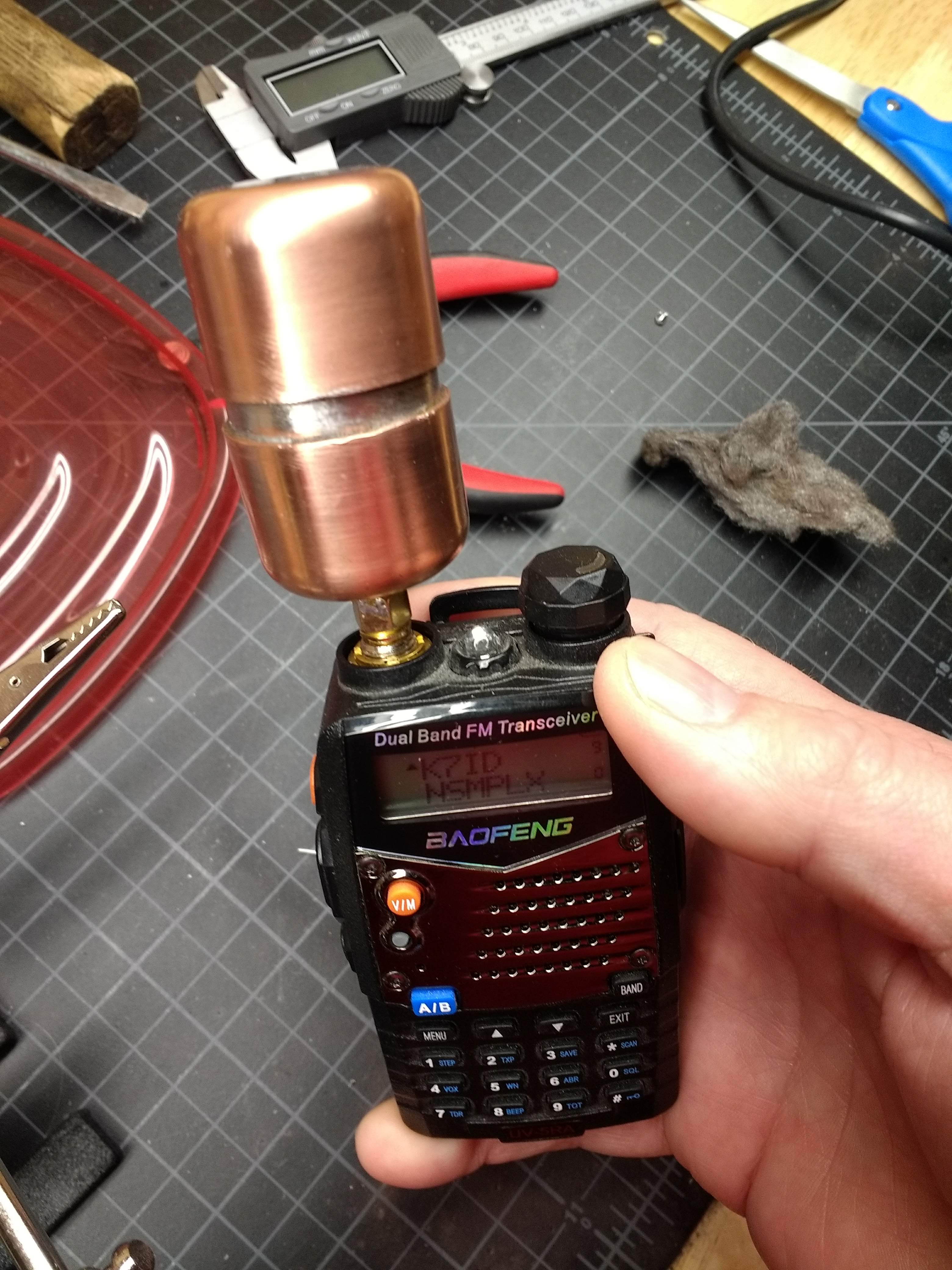
That means our resistive elements need to be as non-inductive as possible. But, they also need to be able to dissipate a lot of power. The HT dummy load, which I’ve dubbed L’il Dummy, needs to handle the 5 to perhaps 8 watts an HT can output. Trouble is, power resistors in that range are often wirewound, and a coil of wire will have too much inductance. We’ll need to be clever in sourcing components.
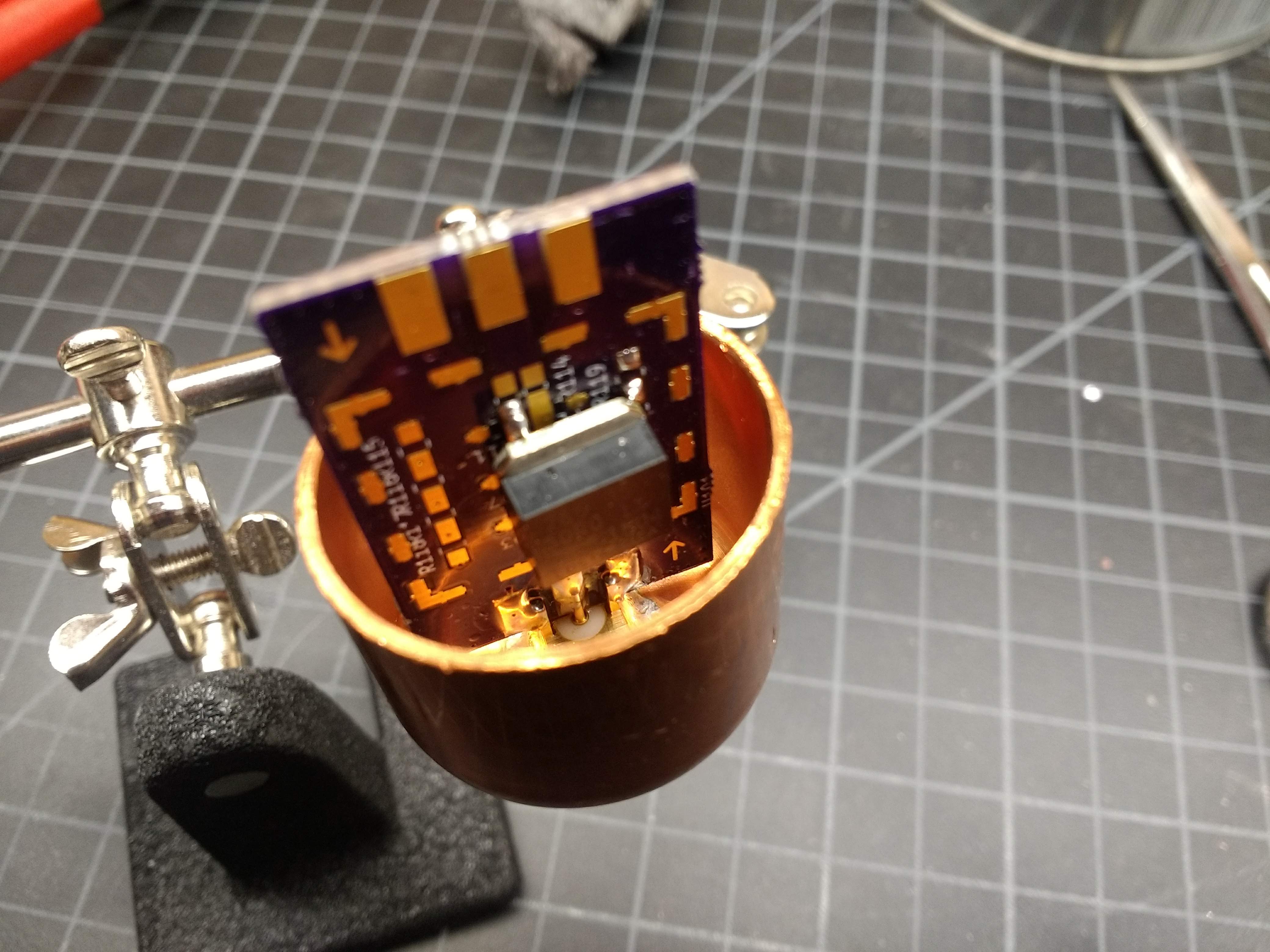
Looking down into L’il Dummy just before applying the torch. The RF Biscuit board is a handy little thing.
The circuit for L’il Dummy is hardly worth a schematic – it’s just an SMA jack with a 50-ohm resistor across the outer ground and the inner conductor. I chose to build the circuit on an RF Biscuit board. This is an open-source design that enables all kinds of handy little RF circuits — attenuators, filters, and as in this case, dummy loads. The resistive element I chose was a thick-film SMT device capable of dissipating 35 watts – way more than enough for this job. That and an edge-mount SMA jack should have been all I needed to make a working dummy load.
To my surprise, once I soldered the resistor to the RF Biscuit board, the dummy load was almost as good an antenna as the stock rubber ducky on my Baofeng HT. I was able to hit a local repeater through the dummy load without any issues. Clearly not a good design. To correct it, I put the whole thing into an enclosure made from 1″ copper pipe. Not cheap stuff, but not too bad, and I like the look of polished copper. Soldering the whole case together was a challenge that my big Weller soldering gun wasn’t up to, and trying to get everything heated up enough with a propane torch without overdoing the heat was a fun time.
Testing on a Budget
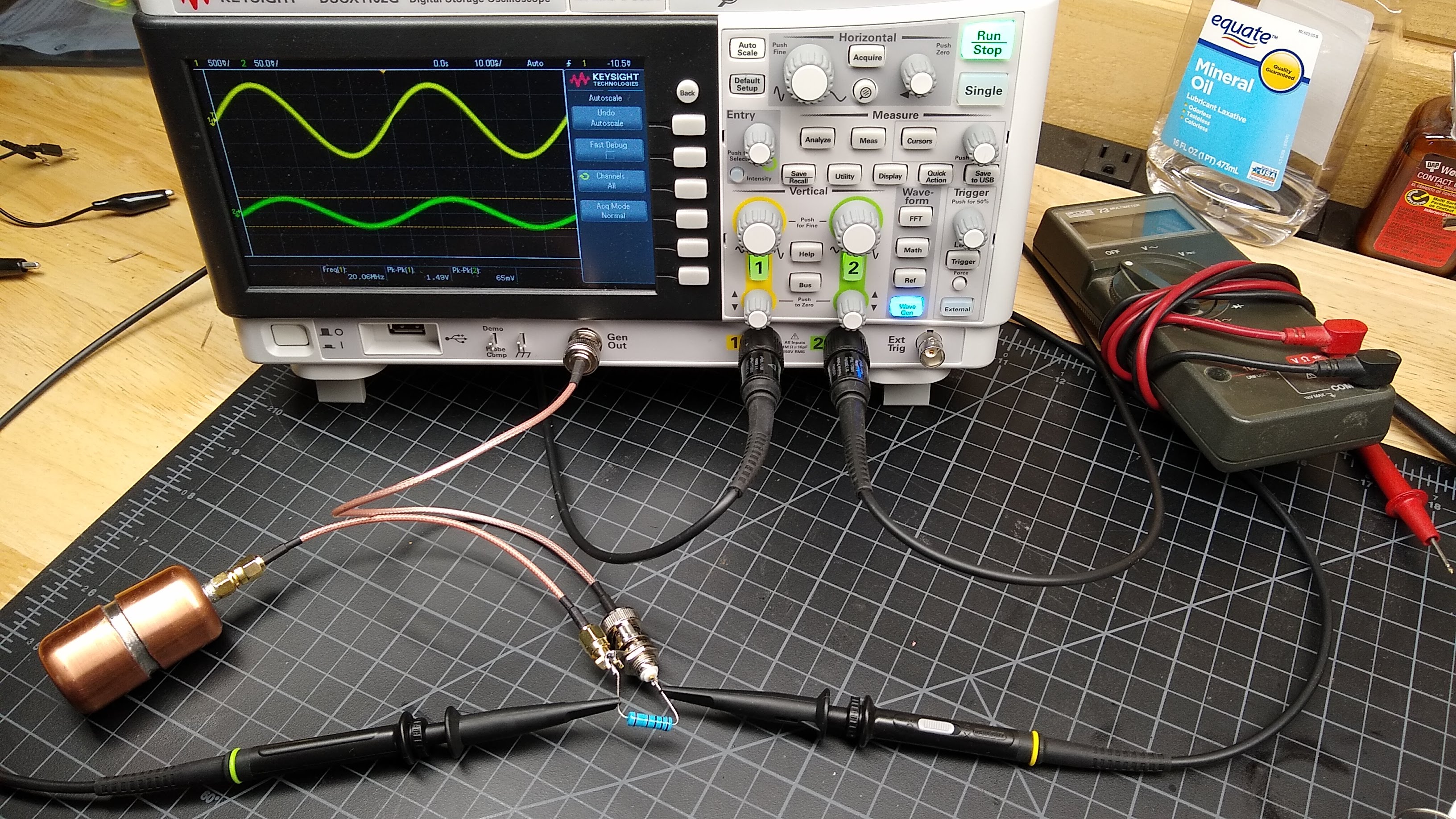
Now for the $50 question: does it work? I tested the resistance with a DMM and it comes out to just about 49 ohms, which is close enough in my book. But that’s DC resistance; what about impedance? I don’t have an antenna analyzer, so I trolled around and found a simple method for measuring impedance with only a function generator and an oscilloscope. My scope has a 20-MHz function generator built in, so I whipped up a quick test jig from a BNC jack and an SMA jack, connected in series through a leftover 1000-ohm resistor.
L’il Dummy test setup. Measure the p-p voltage on each side of the series resistance connecting the function generator to the dummy, and do a little math.
Applying a sine wave into the dummy load, measuring peak-to-peak voltages on each side of the resistance, and doing a little math is all that’s needed to characterize the impedance from 2.5 MHz to 20 MHz. The math is simple:
with V1 being the voltage across the input, V2 being the voltage across the output, and Rref being the actual value of the series resistance, which I measured at 998 Ohms.
And the results are pretty close to 50 Ohms, and flat across the tested band
f (MHz)
V1 (V p-p)
V2 (V p-p)
Z (ohms)
20.0
1.49
0.062
43.3
15.0
1.89
0.082
45.3
10.0
2.57
0.113
45.9
5.0
3.90
0.173
46.3
2.5
4.70
0.217
48.3
I wish I could measure it at VHF and UHF frequencies, but that will have to wait until I get a function generator that goes up to 400 MHz or so. I doubt very much that a $50 budget would cover that, though.
Next Time
I had intended to cover both L’il Dummy and its bigger, somewhat smarter brother in one article, but I still have some testing to do on Big Dummy. I’ll cover that next time, and after that we’ll move onto measuring the output of a cheap Chinese HT and perhaps building a filter to clean it up.
So far in this series, we’ve covered the absolute basics of getting on the air as a radio amateur – getting licensed, and getting a transceiver. Both have been very low-cost exercises, at least in terms of wallet impact. Passing the test is only a matter of spending the time to study and perhaps shelling out a nominal fee, and a handy-talkie transceiver for the 2-meter and 70-centimeter ham bands can be had for well under $50. If you’re playing along at home, you haven’t really invested much yet.
The total won’t go up much this week, if at all. This time we’re going to talk about what to actually do with your new privileges. The first step for most Technician-class amateur radio operators is checking out the local repeaters, most of which are set up exactly for the bands that Techs have access to. We’ll cover what exactly repeaters are, what they’re used for, and how to go about keying up for the first time to talk to your fellow hams.
Time to face some cold, hard facts about amateur radio: that spiffy new Baofeng radio I recommended last time as a great starter radio is actually pretty lame. That fact has little to do with the mere $25 you spent on it, or $40 if you opted to upgrade the antenna. It’s a simple consequence of physics: a radio that transmits at 5 watts will only have so much range on the VHF band, and even less on UHF. Even if you buy a more powerful HT, or invest in a mobile or base-station rig running 50 or 100 watts, the plain fact is that direct radio-to-radio contacts on the same frequency, or simplex contacts, are difficult on VHF and UHF because those bands are really best for line of sight (LOS) use.
That’s not to say that hams don’t use their VHF and UHF rigs for simplex communications, of course. Many hams like to see just how far they can push their signals on these bands, building big Yagi antennas and finding mountain peaks to operate from. But for general use around town, most hams rely on repeaters to extend the area they can communicate over. Repeaters are simply transceivers set up to receive signals on one frequency and transmit them on another at the same time, with the help of a device called a duplexer. This simultaneous reception and transmission gives rise to the term duplex communications, the general term for operating on a repeater.
Repeater usually transmit at a much higher power than an HT or even a mobile rig can manage, and they usually have the advantage of being located on a mountaintop or some other elevated place to gain the furthest possible radio horizon as possible. This arrangement vastly increases the area that you can cover with your tiny HT. Depending on how the repeater is sited and what sort of antenna it has, you may be able to cover hundreds of square miles, as opposed to perhaps a few miles radius under ideal conditions, or a few blocks in the typical urban or suburban setting with lots of clutter from buildings and trees. What’s more, some repeaters are linked to other repeaters either through backhaul connections, often via the Internet but also sometimes through powerful LOS microwave links. In these systems it’s possible to use a puny HT to talk to another ham over hundreds or even thousands of miles. It’s actually pretty cool.
Welcome to the Machine
So where are these repeaters, and how do you start working them? The first question is easy to answer: they’re everywhere. Look at any tall building, mountaintop antenna farm, or municipal water tank, and chances are pretty good there’s a ham repeater there. But being able to work them means you need to know exactly where they are, to be sure you’re in range of the repeater, or “the machine” as hams often refer to it, as well as the frequencies it operates on.
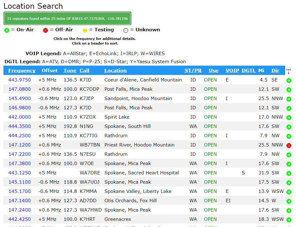
Luckily, there are online guides to help with that chore. RepeaterBook.com is usually the first place hams go to find machines in the area. There you can search by state, county, or city, or even via a map, and find what repeaters are available. They’ve even got a handy road search, so you can get all the repeaters listed as within range of a particular highway; that’s really handy for road-trip planning. Here’s what comes up for VHF and UHF repeaters when I search within 25 miles of my location, or QTH:
The first thing you’ll notice is that several machines at different sites have the same callsign. For example, K7ID runs a UHF repeater on Canfield Mountain and a VHF machine on Mica Peak. Both are LOS to me, and I can easily hit them with an HT. The frequency listed in the first column is the transmit frequency of the repeater. Your HT will need to be set to this frequency to hear what’s being said. Your radio will also need to be programmed for the correct tone, listed in the third column. That tone is an audio frequency signal known by a number of different trade names, but generically as continuous tone-coded squelch system (CTCSS). Your radio is capable of adding this sub-audible tone to your transmission; the repeater will only “open up” to transmissions that are correctly coded. Some repeaters have no tone coding, others have different tones for receive and transmit. When doubt, try to find out who runs the machine – most, but not all, are run by a ham radio club – and see if you can look up instructions on the web.
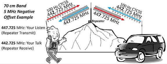
The offset shown in the second column is perhaps the most important bit of information. Recall that repeaters transmit and receive on different frequencies, and that they’re listed by their transmit frequency. The offset tells you what the repeater’s input frequency is, which is the frequency your radio will need to be set to transmit on. For example, the machine I most often used is the K7ID machine on Mica Peak. It’s at 146.980 and shows an offset of -0.6 MHz. That means that my radio has to be set to 146.380 MHz transmission frequency. VHF repeaters are usually 0.6 MHz, but could be plus or minus depending on which part of the VHF band they’re in. UHF repeaters usually have +5 MHz offsets.
Note: I’m not going to cover programming your radio, because there are plenty of guides online that do a better job than I can. DuckDuckGo is your friend.
Casting the Net
Once you’ve found your local repeaters and programmed your radio, it’s time to get on the air. My advice is to spend the first few days just listening to one or more repeaters. Activity levels vary – some machines are hopping all day, and some are barely used except during the typical commuting hours. When you hear a conversation, try to get a feeling for the culture of the repeater. Every group of hams has a culture, and as we discussed in the first installment of the series, it’s not always a healthy culture. My local repeater belongs to the Kootenai Amateur Radio Society, as friendly and as inviting a group of people as I’ve ever heard on the air. After listening to them chat for a few weeks, I was more than ready to reach out to them.
But first, a word about kerchunking. If you want to know if you’re in range of a repeater, you can test it out. Most repeaters have a “squelch tail” that keeps the repeater on the air for several seconds before going back to sleep, and this can be used to check if you’re in range. Some repeaters even identify themselves, either with a synthesized voice or Morse code when they “wake up”. So you might want to ping the repeater.
Kerchunking, or transmitting into a repeater without identifying yourself, is one of those bad habits that everyone seems to have. But FCC part 97 rules, which cover the amateur radio service, require operators to transmit their call sign when they start a transmission. So don’t kerchunk; a simple identification like “This is KC1DJT testing and clear” will suffice. Nobody is likely to take that as an invitation to chat, but they might give you a reception report.
Once you’re feeling confident enough, try making a contact. I highly recommend checking out the local traffic networks. Hams pride themselves on having the skills and equipment to communicate in an emergency, but that means little without practice to keep everything sharp. Nets allow hams to practice message passing skills and to test their gear on a regular basis. My local group has a network check-in every night that follows a standard script and usually attracts about 30 check-ins. Here’s a sample from a recent check-in:
I’ve become a regular on this net and a few others, mainly because I want to practice, but also to get over my mic shyness. There’s another reason too – I want people to recognize my voice and callsign. If there ever is an emergency in my area, I feel like it’ll be easier to pitch in or to get help if I need it if people hear a familiar voice.
Next Time
Over the next few installments, we’re finally going to get to what I think ham radio is all about at its core: homebrewing. We’ll be building a few simple projects to make that cheap HT a little better, and also build a few tools to help run the shack a little more efficiently.
There used to be a time when amateur radio was a fairly
static pursuit. There was a lot of fascination to be had with building
radios, but what you did with them remained constant year on year. Morse
code was sent by hand with a key, voice was on FM or SSB with a few
old-timers using AM, and you’d hear the warbling tones of RTTY traffic
generated by mechanical teletypes.
By contrast the radio amateur of today lives in a fast-paced world of
ever-evolving digital modes, in which much of the excitement comes in
pushing the boundaries of what is possible when a radio is connected to a
computer. A new contender in one part of the hobby has come our way
from [Guillaume, F4HDK], in the form of his NPR, or New Packet Radio mode.
NPR is intended to bring high bandwidth IP networking to radio
amateurs in the 70 cm band, and it does this rather cleverly with a
modem that contains a single-chip FSK transceiver intended for use in
licence-free ISM band applications. There is an Ethernet module and an
Mbed microcontroller board on a custom PCB, which when assembled
produces a few hundred milliwatts of RF that can be fed to an
off-the-shelf DMR power amplifier.
Each network is configured around a master node intended to use an
omnidirectional antenna, to which individual nodes connect.
Time-division multiplexing is enforced by the master so there should be
no collisions, and this coupled with the relatively wide radio bandwidth
of the ISM transceiver gives the system a high usable data bandwidth.
Whether or not the mode is taken up and becomes a success depends
upon the will of individual radio amateurs. But it does hold the
interesting feature of relying upon relatively inexpensive parts, so the
barrier to entry is lower than it might be otherwise. If you are
wondering where you might have seen [F4HDK] before, we’ve previously
brought you his FPGA computer.


 your magic smoke. Even if you are lucky, stray parts are the root of boundless malfunctions from disruptive to deadly. [TheRainHarvester] shares his trick for