AI is currently popular, so [Chirs Lam] figured he’d stimulate some interest in amateur radio by using it to pull call signs from radio signals processed using SDR. As you’ll see, the AI did just okay so [Chris] augmented it with an algorithm invented for gene sequencing.
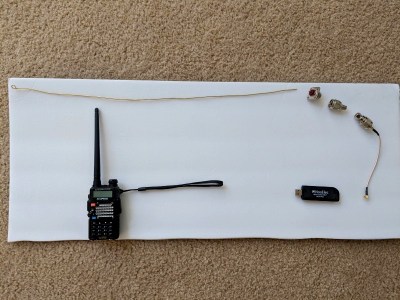
His experiment was simple enough. He picked up a Baofeng handheld radio transceiver to transmit messages containing a call sign and some speech. He then used a 0.5 meter antenna to receive it and a little connecting hardware and a NooElec SDR dongle to get it into his laptop. There he used SDRSharp to process the messages and output a WAV file. He then passed that on to the AI, Google’s Cloud Speech-to-Text service, to convert it to text.
Despite speaking his words one at a time and making an effort to pronounce them clearly, the result wasn’t great. In his example, only the first two words of the call sign and actual message were correct. Perhaps if the AI had been trained on actual off-air conversations with background noise, it would have been done better. It’s not quite the same issue, but we’re reminded of those MIT researchers who fooled Google’s Inception image recognizer into thinking that a turtle was a gun.
Rather than train his own AI, [Chris’s] clever solution was to turn to the Smith-Waterman algorithm. This is the same algorithm used for finding similar nucleic acid sequences when analyzing genes. It allowed him to use a list of correct call signs to find the best match for what the AI did come up with. As you can see in the video below, it got the call signs right.
With any hobby, it’s easy for things to get out of hand. Equipment can get scattered around the house, chargers lost in the car while cables languish in the shed… but it doesn’t have to be this way. With a go-bag or go-box, everything required is kept together in a ready-to-go condition. Heading out for a day of filming? Grab the go-bag and you’re all set. [oliverkrystal] wanted to apply this to a ham radio setup, and built this ham shack-in-a-box.
Wanting to use proven components and keep things rugged and usable, the build starts with a 6U-sized plastic rack mount case. This saves weight over plywood versions and is nice and tough. A combination of off-the-shelf rack mount parts and 3D printed pieces are brought together to make it all happen. [oliverkrystal]’s printed cable organisers are a particular treat, and something we think could help a lot of builds out there.
It all comes together as an impressive self-contained unit with two radios, an antenna tuner, in-built illumination and other useful features. No longer does one have to scramble around preparing gear for the weekend’s hamventures – grab the box and you’re ready to go!
Chances are you have at least one radio that can receive FM stations. Even though FM is becoming less used now with Internet and satellite options, it still is more popular than the older AM radio bands. FM was the brainchild of an inventor you may have heard of — Edwin Armstrong — but you probably don’t know the whole story. It could make a sort of radio-themed soap opera. It is a story of innovation, but also a story of personal vanity, corporate greed, stubbornness, marital problems, and even suicide. The only thing missing is a long-lost identical twin sibling to turn it into a full telenovela.
Early Days
Armstrong grew up in New York and because of an illness that gave him a tic and caused him to be homeschooled, he was somewhat of a loner. He threw himself into his interest in electric and mechanical devices. By 1909 he was enrolled in Columbia University where professors noted he was very focused on what interested him but indifferent to other studies. He was also known as someone more interested in practical results than theory. He received an electrical engineering degree in 1913.
Unlike a lot of college graduates, Armstrong didn’t go work for a big firm. Instead, he set up a self-financed independent lab at Columbia. This sounded good because it meant that he would own the patents on anything invented there. But it would turn out to be a two-edged sword.
Tubes and Villians
Every good story needs a villain or two, and this one is no exception. The first one is Lee de Forest, the man who invented the triode. History hasn’t painted de Forest kindly, and some of the reasons for that are because of his interactions with Armstrong. However, there’s more than that.
Technically, Thomas Edison invented the vacuum tube as an offshoot of experimenting with light bulbs. He knew electrons were streaming away from the filament and put an electrode in — what we would call a plate — to collect them. He didn’t have any real idea what to do with the device, though.
In 1904 John Fleming realized that the device operated like a check valve allowing current to flow in one direction but not the other and demonstrated using it as a rectifier. This is why people in some parts of the world call tubes Fleming valves.
What de Forest added to the mix was to put a grid between the filament and the plate. He was actually trying to build a radio detector that used ionized gasses and filed a patent on a two-terminal device in 1907. The grid was initially on the outside of the glass tube, which didn’t work well. Once it was moved inside the tube, it allowed a small signal on the grid to be amplified at the plate. De Forest called this tube the audion. There were a few reasons it didn’t work very well, not the least of which is that de Forest erroneously thought that having a little gas left in the tube was essential for its operation. We know now, you want less gas, not more.
This all fits in with the historical accounts that de Forest didn’t fully understand the tube. He was just trying different things to see what would work — not always a bad thing, especially in those days where others worked with a similar methodology. He even reportedly said:
I have arrived, as yet, at no completely satisfactory theory as to the exact means by which the high-frequency oscillations affect so markedly the behavior of an ionized gas.
If he was just a practical inventor, that wouldn’t make him a villain, though. However, when Marconi, who held the Fleming patent, sued that the audion infringed, de Forest took the position that the two devices were completely different. Of course, they were not. A court sided with Marconi although since the grid was a patentable improvement, so the two sides agreed to exchange rights.
We think of protracted court battles over intellectual property as a modern problem. Perhaps it is true that the more things change, the more they stay the same.
Back to Armstrong
Armstrong grew up experimenting with gassy low-quality audions. He was determined to understand how the device worked in a scientific way. While at Columbia he did comprehensive studies and found that using positive feedback could create much higher amplification — enough to drive speakers instead of headphones. This is the basis behind a regenerative receiver. The signal is amplified many times over getting stronger each time. In addition, Armstrong learned that if you increase the feedback, you get sustained oscillations. This would be a huge breakthrough for radio to have a reliable way to generate radio waves electronically.
Armstrong filed for a patent in 1913. Lee de Forest predictably discounted Armstrong’s work for a few years. Then in a surprise move in 1915 he filed patents for the same inventions claiming he had priority because of a lab notebook he had dated in 1912. World War I intervened, however, so things moved slowly.
Regenerative receivers were sold until another Armstrong invention would replace them. Regens are still popular with hackers because they generally have a very low parts count. If you want to learn more about how they work, check out Stan’s video analysis of one based on a FET which isn’t very different from a tube.
War Time
During the war, Armstrong also developed the superheterodyne receiver: a common architecture even today where a frequency of interest is converted to a single intermediate frequency for amplification and filtering prior to detection.
By 1919 Armstrong was in court on two fronts on the de Forest patents. To finance his legal fees, he had licensed several companies to make regenerative receivers for amateurs and experimentation. He was also shopping for a big corporation to buy the rights. Westinghouse wound up with both the regenerative and superheterodyne patents. By 1928, the courts would actually decide a Frenchmen named Lévy invented the superheterodyne first.
The Regenerative Patent
The legal front on regeneration was quite different. Both the court and the patent office decided that de Forest’s patents were not valid. However, Armstrong didn’t want to settle for the compensation offered by de Forest. This allowed de Forest to appeal the case, which he eventually won through two further appeals up to the Supreme Court.
This move shocked most people in the radio business at the time. Armstrong attempted to return an award he received from the IRE (the Institute of Radio Engineers) and the institute refused to accept the return, publically stating they rejected the court’s findings.
Although Armstrong didn’t do well in court, he did have a little luck. While dealing with the legal end of things, he stumbled on an improvement to regeneration called super regeneration. That patent netted him $200,000 and 80,000 shares of RCA stock which made him the largest shareholder. Keep in mind, too, that $200,000 in 1922 was a fortune. RCA wound up never actually producing radios using this technology, as the superheterodyne turned out to be far superior.
Which Brings us to FM…
In case you forgot, all this was leading into the invention of FM radio. AM radio is very prone to noise and fading because these show up as changes in amplitude — the A in AM. During the 1920s, Armstrong was trying to think of ways to improve AM radio. FM — modulating frequency instead of amplitude — had been largely dismissed because of an incomplete analysis of FM done by John Carson showing that FM would not improve on the quality of AM.
By 1928, Armstrong started working with FM despite its detractors, and the key was using a wider bandwidth. Armstrong filed for patents in 1933. RCA had the right of first refusal on his patents by this time, but they were unimpressed with a system that was complex and was not compatible with existing equipment.
Armstrong went to smaller radio companies like General Electric and Zenith. He also got the FCC to allocate a band for this new kind of radio with 40 channels in the 42 to 50 MHz range. You might notice that this isn’t where the FM band is today. That will play a part in the story to come. There’s a lot of pictures of old FM radios, for this band online. Oddly enough, this band displaced another attempt to do “better” radio called Apex radio — a topic we will cover in the near future.
The Million Dollar Question
At first, RCA saw FM as a threat to their existing businesses and did everything they could to prevent Armstrong from demonstrating the system to the public. Despite this, Armstrong did get the FCC interested in FM and even built his own FM station W2XMN to help get things moving.
The first broadcast was in 1939. There were only 25 FM receivers in the world at that time, so the audience wasn’t very large.
RCA finally wanted to get into the FM game, but they didn’t want to pay Armstrong royalties. In 1940, they offered him a cool million dollars for a non-exclusive but royalty-free license. Armstrong didn’t feel like it was fair to other companies that were paying 2% on their sales. He refused and this would become a fateful and ultimately pointless decision.
To the right, you can see a magazine cover from 1940. The picture shows a million volt arc that totally ruins AM reception but didn’t interfere at all with the FM radio.
Band Adjustment
Because of World War II, there were comparatively few FM receivers and stations in service on the new frequency band. I say comparatively because ultimately there would be nearly 400,000 receivers in service compared with millions of AM radios.
Signals around 50 MHz are subject to propagation effects that can cause interference. RCA lobbied fiercely to move the FM band and Armstrong vigorously countered it. In his opinion, RCA only wanted to disrupt the existing base of FM stations and receivers, perhaps because he wasn’t willing to take their million dollar offer.
Since you know the current FM band is from 88 to 108 MHz, you can probably guess which side won in 1945. Still, Armstrong was convinced that FM was the future and even hired a public relations firm to spread the word about FM’s superiority.
RCA would eventually develop what they claimed were non-infringing FM patents and even encouraged other companies to stop paying royalties to Armstrong. He sued, but RCA was able to tie the case up for years.
The Bitter End
The two obvious villains in this story were de Forest and David Sarnoff of RCA. However, there’s a third villain: the courts. Being constantly embroiled in legal battles with a giant company takes its toll on your pocketbook and on your mental health.
Facing bankruptcy, Armstrong approached his wife Marion (who had been, by the way, David Sarnoff’s secretary) about returning money he had given her to put aside for their retirement. She refused and in 1954 he took a swing at her with a fire poker. Unsurprisingly, she left him.
Armstrong lived in an apartment on the 13th floor of the New York River House. With his wife gone and three servants done for the day, Armstrong removed an air conditioning unit, put on a nice suit, a hat, overcoat, and gloves. Then after writing a two-page note, he walked out the window, plummeting to his death on a third-floor balcony. The New York Times reported that he was heartbroken over the loss of his wife and regretted hurting her.
It is ironic that Armstrong turned down the million dollars. After his death, Marion settled with RCA for — what else — a million dollars. She also pursued other court cases, defending his patents and receiving infringement awards from other manufacturers. FM would really take off after General Electric added stereo to FM in the late 1950s.
A sad end to a prolific inventor that created a lot of technology we still use today. It is hard to say for sure if the villains in a story like this were really as bad as they appear or just unable to present their side of the story. On the other hand, history is written by the victors and Armstrong certainly wasn’t the victor. That’s got to mean something.
As I was writing this, though, one thing did strike me. Most of the world — including the United States — has gone to a patent system where “first to file” gets priority. I’ve always thought that is bad for us hackers because we are less likely to quickly file patents and, thus, more likely to get knocked out by a big company spewing out dozens of patent disclosures a day. But this is a case where first to file might have totally changed Armstrong’s life for the better. It also reminds me that even though most of us don’t file patents often, maybe we should think about it. Maybe big companies are going to control all the upcoming innovations because — unlike Armstrong — we are letting them.
It’s easy to dismiss radio as little more than background noise while we drive. At worst you might even think it’s just another method for advertisers to peddle their wares. But in reality it’s a snapshot of the culture of a particular time and place; a record of what was in the news, what music was popular, what the weather was like, basically what life was like. If it was important enough to be worth the expense and complexity of broadcasting it on the radio, it’s probably worth keeping for future reference.
But radio is fleeting, a 24/7 stream of content that’s never exactly the same twice. Yet while we obsessively document music and video, nobody’s bothering to record radio. You can easily hop online and watch a TV show that originally aired 50 years ago, but good luck finding a recording of what your local radio station was broadcasting last week. All that information, that rich tapestry of life, is gone and there’s nothing we can do about it.
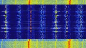
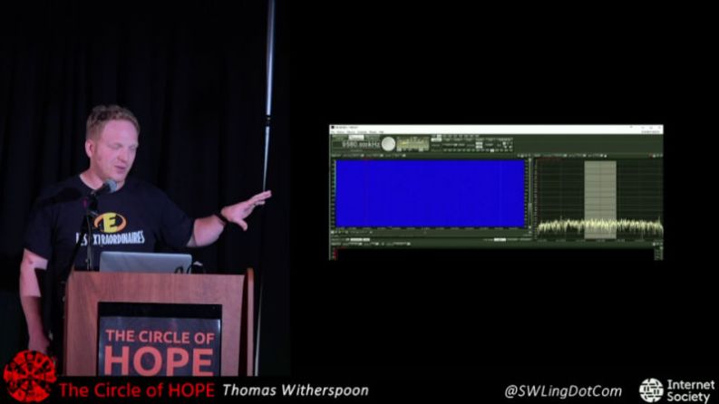
Or can we? At HOPE XII, Thomas Witherspoon gave a talk called “Creating a Radio Time Machine: Software-Defined Radios and Time-Shifted Recordings”, an overview of the work he’s been doing recording and cataloging the broadcast radio spectrum. He demonstrated how anyone can use low cost SDR hardware to record, and later play back, whole chunks of the AM and shortwave bands. Rather than an audio file containing a single radio station, the method he describes allows you to interactively tune in to different stations and explore the airwaves as if it were live.
Modern Take on a Classic Technique
You might think that such radio trickery is a product of modern hardware and software, but in fact the methods Thomas and his group of radio archivists use have considerably more retro beginnings. As far back as the 1980’s DXers, radio hobbyists that look specifically for distant signals, found that if they connected the intermediate frequency (IF) output of their radio to a VCR they could capture whatever their antenna was picking up for later analysis. When the tape was played back through the antenna port of the radio, they could tune to individual frequencies and search for hard to hear signals.
Of course the utility of this method wasn’t limited to just weak signals. It allowed radio operators to do things that would otherwise be impossible, like going back and listening to different news broadcasts that were aired at the same time. A few DXers realized there was a potential historical value to such recordings, and some of these early tapes were saved and wound up becoming part of the collection Thomas has been building and offering up as a podcast.
The modern version of this technique replaces the AM or shortwave receiver with any one of a number of affordable SDR devices, and the VCR has become a piece of software that can dump the SDR’s output to a file. This file can then be loaded up in a compatible SDR interface program, such as HDSDR, in place of an actual radio.
Storing History
Thomas envisions a future where researchers will be able to sit down at a kiosk and browse through the radio broadcasts from a given time and place, the same way a microfilm machine is used to look at a newspaper from decades past. But while making these recordings is now cheaper and easier than ever before, there are still logistical issues that need to be solved before that can happen. Chief among them: how do you store it all?
Thomas mentions that a single day’s recording of the AM broadcast band will result in roughly 1 TB of data. Potentially some compression scheme could be developed which would scan the recordings to isolate the viable signals and delete the rest. Another approach would be a sort of ring buffer arrangement, where the system only retains the last few days of recordings unless the user commits them to long-term storage. If something deemed worthy of future study occurs, the ring buffer could be moved to permanent storage so the event as well as the preceding time could be preserved for historical purposes.
Until then, Thomas and his team will keep on recording during noteworthy events. As an example, they made extensive spectrum recordings during the 2016 US Presidential elections, believing it will be a moment future generations will likely want to have as much information on as possible.
Unless you live in a cave, you’ve probably heard a little about the thirteen people — mostly children — trapped in the Tham Luang Nang Non cave in Thailand. What you may have missed, though, is the hacker/ham radio connection. The British Cave Rescue Council (BCRC) was asked for their expert help. [Rick Stanton], [John Volanthen] and [Rob Harper] answered the call. They were equipped with HeyPhones. The HeyPhone is a 17-year-old design from [John Hey, G3TDZ]. Sadly, [G3TDZ] is now a silent key (ham radio parlance for deceased) so he didn’t get to see his design play a role in this high-profile rescue, although it has apparently been a part of many others in the past.
The HeyPhone is actually considered obsolete but is still in service with some teams. The radio uses USB (upper sideband, not universal serial bus) at 87 kHz. The low frequency can penetrate deep into the ground using either induction loop antennas like the older Molephone, or — more commonly — with electrodes injecting RF energy directly into the ground.
You can find a very detailed article about the radio from 2001 if you want more details. The system is somewhat dated, but apparently works well and that’s what counts.
What we find interesting is that in today’s world, people take wireless communications for granted and don’t realize that cell phones don’t work underground or in the face of widespread disasters. We would imagine most Hackaday readers know how cell phone towers use “cellular reuse” to support more than a handful of phones. Ask some non-technical friend if they know how a cell phone works and you’ll be surprised how few people understand this. Ham radio operators and hackers are vital to building and deploying specialized radio systems in times of disaster or — in this case — where people need rescuing from an odd environment.
We were glad to see a nod to some hacker gear in the popular press. But we almost wish there had been more reporting on the volunteer divers and their hacked radio gear.
If you search through an electrical engineering textbook, you probably aren’t going to find the phrase “gimmick capacitor” but every old ham radio operator knows about them. They come in handy when you need a very small capacitor of unknown value. For example, if you are trying to balance the stray capacitance in a circuit, you might not know exactly what value you need, but you know it won’t be very much. That’s when you want a gimmick capacitor.
A gimmick capacitor is made by taking two strands of insulated wire and twisting them together; the length and the tightness of the twist determine the capacitance. Tightening or loosening the twist, or trimming some of the wire off, makes it tunable.
These are most commonly found in RF equipment or high-speed logic because of the small capacitance involved — usually about 1 to 2 pF per inch of twist or so. The thicker the insulation, the less capacitance you’ll get, so it is common to use magnet wire or something else with a thin insulating layer. You can take this one step further and decrease the spacing by stripping down one wire as long as it isn’t going to touch anything else.
Obviously, the insulation needs to be good enough for the voltage on them, an important consideration in tube circuits, for instance. But other than that, a gimmick capacitor is a straightforward tool to have in your box of design tricks. Can we take this further?
PC Board Gimmicks
You might wonder if the technique can be applied to PC boards. The answer is yes — sort of. Unless you use very thin boards, or thin layers in multilayer boards, it takes a lot of board real estate to get even a small capacitance. Also, typical PCB material can change over time with moisture or other effects. Practically, unless you use special board material and thicknesses, it isn’t very useful. There has been work on laying out linear capacitors on IC substrates using fractals, but we aren’t sure how that would translate into a PCB layout. We’ve seen lots of other PC trace components like antennas, shunt resistors, inductors, and transmission lines.
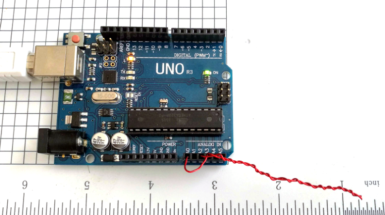
You can see I made a gimmick just bigger than two inches. I then went looking for something around the lab that had the ability to measure such a small capacitor. The component tester couldn’t. I have a nice digital multimeter that has a special plug-in for measuring capacitors and thermocouples, but it wouldn’t reliably read anything under 25 pF. I was thinking about building up a circuit to test when I realized I should search Hackaday first.
Hackaday Saves the Day
[Jonathan’s] capacitance meter is just what I needed and I even threw it out to an Arduino that was already hooked up using the Arduino Create web interface, so that was easy. I actually used the newer “Mark II” code but it works the same for the low values I was measuring. I calibrated with a garden variety 10 pF ceramic. It probably isn’t that accurate, but I really only wanted to see the change more than the actual value, so I thought this was sufficient.
The two inch (call it 6 cm) gimmick reads about 5.5 pF. That might not be totally accurate, but I was expecting about 4.5 pF and the magnet wire insulation is quite thin, so it’s in the right ballpark. Let’s take it as a baseline to measure change. I then cut about 1.5 cm of the capacitor away — about 25% — and the reading became 3.7 pF. Another centimeter brought it down to 2.6 pF.
Of course, hand-wound pitch isn’t very accurate, nor were my cuts or measurements, but that works out to just around 1 pF per centimeter. Obviously, your results are going to depend on your winding and the kind of wire you use. [Harry Lythall] suggests folding a single piece of wire, holding it with pliers, and twisting. Then you cut the loop when you are done.
That’s a Wrap
It is easy to forget that any two conductors near each other will have capacitance. Another common makeshift capacitor is a length of coax with connections at one end and open at the other. RG-8, for example, is about 30 pF per foot of cable. There’s even an online calculator that will tell you how much coax you need for any given value. This varies by coax type, of course, so remember to cut a little long and trim!
The next time you need a small adjustable capacitor — especially in a lab setting — don’t forget about the gimmick. Be sure to experiment with different kinds of wire if you are trying for larger values. We’ve seen this trick used in RF filters. In the case of the gimmick, you may be thinking small, but when you are really looking for high voltage capacitors, you can make those, too.
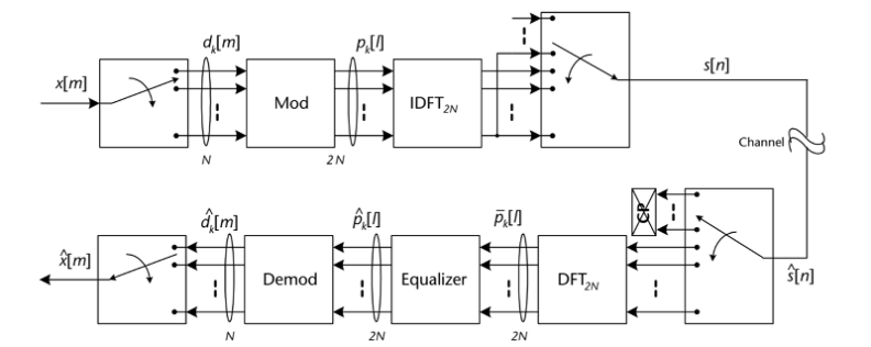
We really like when a vendor finds a great book on a topic — probably one they care about — and makes it available for free. Analog Devices does this regularly and one you should probably have a look at is Software Defined Radio for Engineers. The book goes for $100 or so on Amazon, and while a digital copy has pluses and minuses, it is hard to beat the $0 price.
The book by [Travis F. Collins], [Robin Getz], [Di Pu], and [Alexander M. Wyglinski] covers a range of topics in 11 chapters. There’s also a website with more information including video lectures and projects forthcoming that appear to use the Pluto SDR. We have a Pluto and have been meaning to write more about it including the hack to make it think it has a better RF chip inside. The hack may not result in meeting all the device specs, but it does work to increase the frequency range and bandwidth. However, the book isn’t tied to a specific piece of hardware.
Make no mistake, the book is a college-level textbook for engineers, so it isn’t going to go easy on the math. So if the equation below bugs you, this might not be the book you start with:
[Di Pu] and [Alexander Wyglinksi] have an older similar book, and it looks like the lecture videos are based on that book (see video below). The projects section on the website doesn’t appear to have any actual projects in it yet, although there are a couple of placeholders.
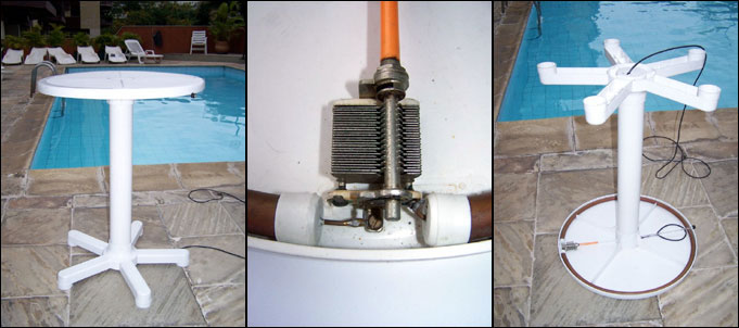
We’re sure all radio amateurs must have encountered the problem faced by [Alexandre Grimberg PY1AHD] frequently enough that they nod their heads sagely. There you are, relaxing in the sun on the lounger next to the crystal-blue pool, and you fancy working a bit of DX. But the sheer horror of it all, a tower, rotator, and HF Yagi would ruin the aesthetic, so what can be done?
[Alexandre]’s solution is simple and elegant: conceal a circular magnetic loop antenna beneath the rim of a circular plastic poolside table. Construction is the usual copper pipe with a co-axial coupling loop and a large air-gapped variable capacitor, and tuning comes via a long plastic rod that emerges as a discreet knob on the opposite side of the table. It has a 10 MHz to 30 MHz bandwidth, and should provide a decent antenna for such a small space. We can’t help some concern about how easy to access that capacitor is, on these antennas there is induced a surprisingly large RF voltage across its vanes, and anyone unwary enough to sit at the table to enjoy a poolside drink might suffer a nasty RF burn to the knee. Perhaps we’d go for a remotely tuned model instead, for this reason.
It used to be homebrew ham gear meant something simple. A couple of active devices that could send CW. Maybe a receiver with a VFO. But only the most advanced builders could tackle a wide range SSB transceiver. Today, that goal is still not trivial, but it is way easier due to specialty ICs, ready access to high-speed digital signal processing, and advances in software-defined radio techniques. [Charlie Morris] decided to build an SSB rig that incorporated these technologies and he shared the whole process from design to operation in a series of nine videos. You can see the first one below.
The NE612 is a child of the popular NE602 chip, which contains a Gilbert-cell mixer, and an oscillator that makes building a receiver much easier than it has been in the past. The chips are set up as direct conversion receivers and feed a Teensy which does the digital signal processing on the recovered audio.
One nice thing about the Teensy is that it has an accessory audio board that makes it easy to connect audio inputs and outputs to the device. The DSP does work on the received audio and the transmit audio. There’s also a few other stock parts like an LCD, an encoder, a speaker, a microphone, and things like that. There’s also a digital clock generator (an Si5351), but again all that is common off-the-shelf stuff these days.
The first video is a bit introductory, but by video number two he jumps right into the wiring and why all the circuits work. By the third video, the receiver is actually working and it sounds pretty good. Because the receiver needs I and Q outputs, there are actually two NE612s operating out of phase with each other.
Sometimes the best projects are the simple, quick hits. Easily designed, fast to build, and bonus points for working right the first time. Such projects very often lead to bigger and better things, which appears to be where this low-power temperature beacon is heading.
In the world of ham radio, beacon stations are transmitters that generally operate unattended from a known location, usually at limited power (QRP). Intended for use by other hams to determine propagation conditions, most beacons just transmit the operator’s call sign, sometimes at varying power levels. Any ham that can receive the signal will know there’s a propagation path between the beacon and the receiver, which helps in making contacts. The beacon that [Dave Richards (AA7EE)] built is not a ham beacon, at least not yet; operating at 13.56 MHz, it takes advantage of FCC Part 15 regulations regarding low-power transmissions rather than the Part 97 rules for amateur radio. The circuit is very simple — a one-transistor Colpitts oscillator with no power amplifier, and thus very limited range. But as an added twist, the oscillator is keyed by an ATtiny13 hooked to an LM335 temperature sensor, sending out the Celsius and Fahrenheit temperature in Morse every 30 seconds or so. The circuit is executed in Manhattan style, which looks great and leaves plenty of room for expansion. [Dave] mentions adding a power amp and a low-pass filter to get rid of harmonics and make it legal in the ham bands.
Beacons are just one of the ways for hams to get on the air without talking. Another fun way to analyze propagation is WSPR, which is little like an IoT beacon.
 His experiment was simple enough. He picked up a Baofeng handheld radio transceiver to transmit messages containing a call sign and some speech. He then used a 0.5 meter antenna to receive it and a little connecting hardware and a NooElec SDR dongle to get it into his laptop. There he used SDRSharp to process the messages and output a WAV file. He then passed that on to the AI, Google’s Cloud Speech-to-Text service, to convert it to text.
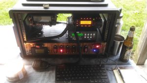


 It’s easy to dismiss radio as little more than background noise while we drive. At worst you might even think it’s just another method for advertisers to peddle their wares. But in reality it’s a snapshot of the culture of a particular time and place; a record of what was in the news, what music was popular, what the weather was like, basically what life was like. If it was important enough to be worth the expense and complexity of broadcasting it on the radio, it’s probably worth keeping for future reference.