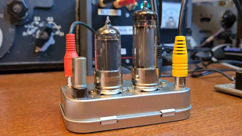
It’s been a long time since vacuum tubes were cutting-edge technology, but that doesn’t mean they don’t show up around here once in a while. And when they do, we like to feature them, because there’s still something charming, nay, romantic about a circuit built around hot glass and metal. To wit, we present this compact two-tube “spy radio” transmitter.
From the look around his shack — which we love, by the way — [Helge Fykse (LA6NCA)] really has a thing for old technology. The typewriter, the rotary phones, the boat-anchor receiver — they all contribute to the retro feel of the space, as well as the circuit he’s working on. The transmitter’s design is about as simple as can be: one tube serves as a crystal-controlled oscillator, while the other tube acts as a power amplifier to boost the output. The tiny transmitter is built into a small metal box, which is stuffed with the resistors, capacitors, and homebrew inductors needed to complete the circuit. Almost every component used has a vintage look; we especially love those color-coded mica caps. Aside from PCB backplane, the only real nod to modernity in the build is the use of 3D printed forms for the coils.
But does it work? Of course it does! The video below shows [Helge] making a contact on the 80-meter band over a distance of 200 or so kilometers with just over a watt of power. The whole project is an excellent demonstration of just how simple radio communications can be, as well as how continuous wave (CW) modulation really optimizes QRP setups like this.
The amateur radio community often gets stereotyped as a hobby with a minimum age requirement around 70, gatekeeping airwaves from those with less experience or simply ignoring unfamiliar beginners. While there is a small amount of truth to this on some local repeaters or specific frequencies, the spectrum is big enough to easily ignore those types and explore the hobby without worry (provided you are properly licensed). One of the best examples of this we’ve seen recently of esoteric radio use is this method of using packet radio to play a game of Colossal Cave Adventure.
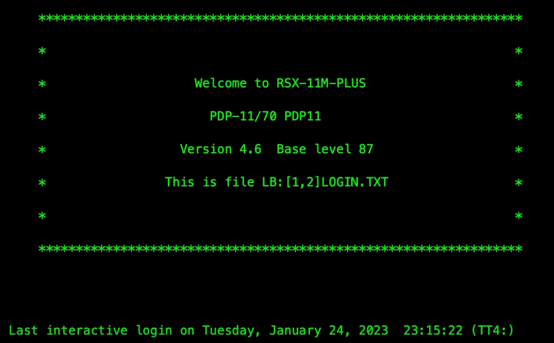
Packet radio is a method by which digital information can be sent out over the air to nodes, which are programmed to receive these transmissions and act on them. Typically this involves something like email or SMS messaging, so playing a text-based game over the air is not too much different than its intended use. For this build, [GlassTTY] aka [G6AML] is using a Kenwood TH-D72 which receives the packets from a Mac computer. It broadcasts these packets to his node, which receives these packets and sends them to a PDP-11 running the game. Information is then sent back to the Kenwood and attached Mac in much the same way as a standard Internet connection.
The unique features of packet radio make it both an interesting and useful niche within the ham radio community, allowing for all kinds of uses where data transmission might otherwise be infeasible or impossible. A common use case is APRS, which is often used on VHF bands to send weather and position information out, but there are plenty of other uses for it as well.
After passing an exam and obtaining a license, an amateur radio operator will typically pick up a VHF ratio and start talking to other hams in their local community. From there a whole array of paths open up, and some will focus on interesting ways of bouncing signals around the atmosphere. There are all kinds of ways of propagating radio waves and bouncing them off of various reflective objects, such as the Moon, various layers of the ionosphere, or even the auroras, but none are quite as fleeting as bouncing a signal off of a meteor that’s just burned up in the atmosphere.
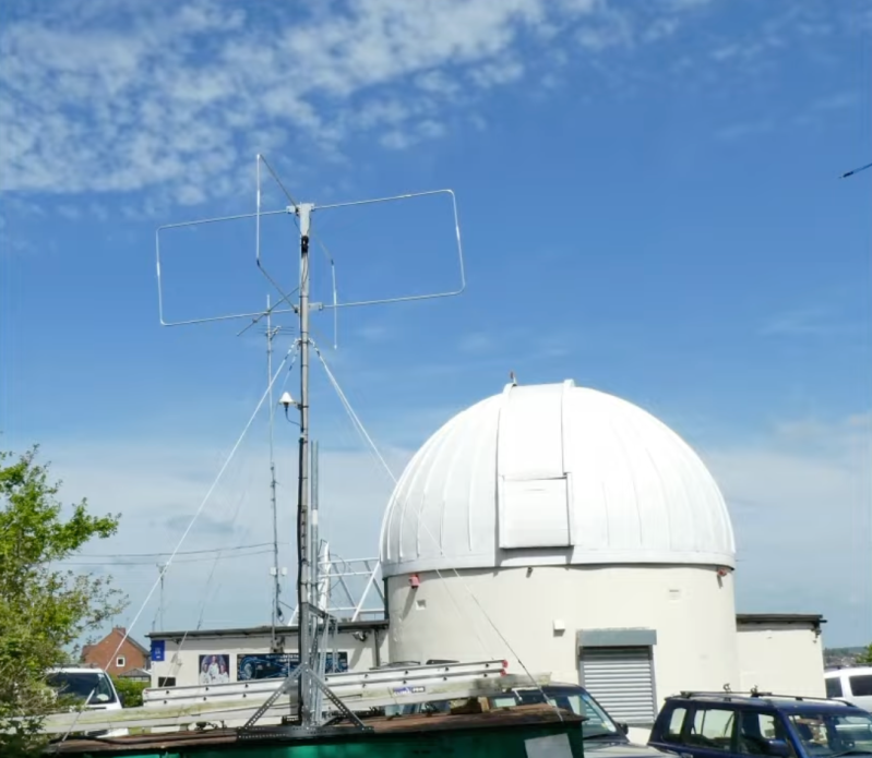
While they aren’t specifically focused on communicating via meteor bounce, The UK Meteor Beacon Project hopes to leverage amateur radio operators and amateur radio astronomers to research more about meteors as they interact with the atmosphere. A large radio beacon, which has already been placed into service, broadcasts a circularly-polarized signal in the six-meter band which is easily reflected back to Earth off of meteors. Specialized receivers can pick up these signals, and are coordinated among a network of other receivers which stream the data they recover over the internet back to a central server.
With this information, the project can determine where the meteor came from, some of the properties of the meteors, and compute their trajectories by listening for the radio echoes the meteors produce. While this is still in the beginning phases and information is relatively scarce, the receivers seem to be able to be built around RTL-SDR modules that we have seen be useful across a wide variety of radio projects for an absolute minimum of cost.
With a UHF antenna, it is easy to rotate a directional antenna to find the bearing to a transmitter. But at HF, it is more common to use an array of antennas that you can electrically switch as well as analyze the phase information between the elements. [Ringway Manchester] has a look at the “elephant cage” antenna used by the US Iron Horse listening network from the 1950s. You can see a video about the giant antenna system, the AN/FLR-9.
Technically, the ring of concentric antenna elements forms a Wullenweber antenna. The whole thing consists of three rings built on a ground screen nearly 1,500 feet across. The outer ring covers from 1.5 to 6 MHz or band A. The band B ring in the center covers 6 to 18 MHz. The inner ring covers band C which was from 18 to 30 MHz. Band A was made up of 48 monopoles while band B used 96 elements. The much smaller band C elements were 48 pairs of horizontally polarized dipoles.
These listening posts could, together, locate an HF signal up to 4,000 nautical miles away. The Wullenweber design, as you may have guessed from the name, originated with the German navy during World War II. It found use in several other systems, although they are relatively rare today, with all of the AN/FLR-9 sites gone.
Cold war hardware is always interesting even if sometimes terrifying. If you think a giant shortwave direction finder is high-tech, you should check out how the Russians bugged IBM Selectric typewriters for a long time undetected.
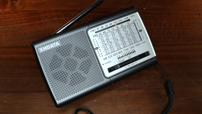
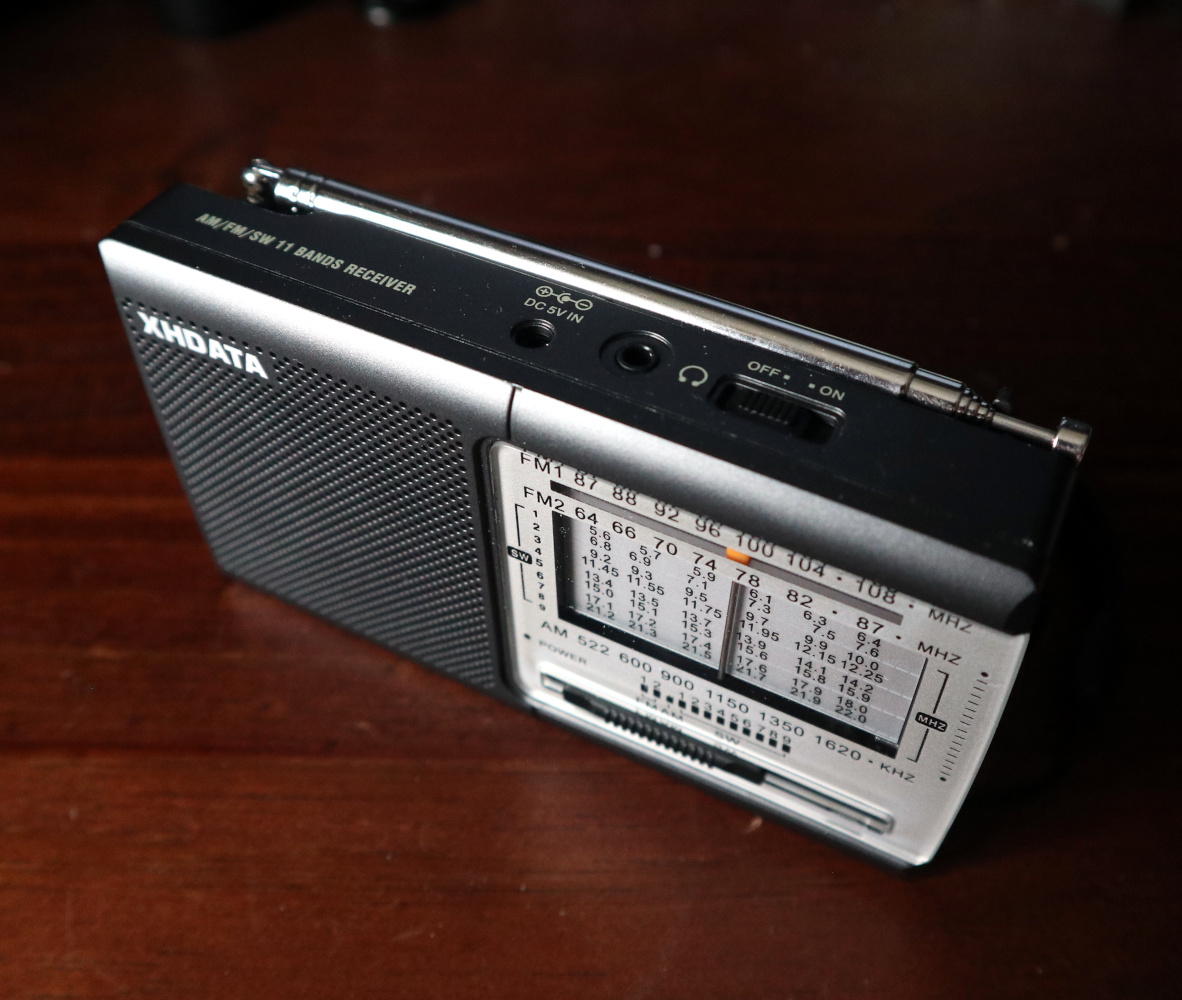
As any radio amateur will tell you, the world of radio abounds with exciting possibilities. Probably the simplest pursuit of them all is that of the SWL, or short wave listener, who scours the airwaves in search of interesting stations. SWLs will often have fully-featured setups with high-end general-coverage communications receivers and tuned antenna arrays, but it can start with the cheapest of radios at its bottom end. Such a radio is the subject of this review, the XHDATA D-219 is a miniature portable receiver that costs under ten dollars, yet is currently the talk of the town in SWL circles. This interest is in no small amount due to its being an especially low-price way to get your hands on a shortwave radio using one of the SIlicon Labs integrated software-defind radio receiver chips. We don’t often review a consumer radio here at Hackaday, but with an avid eye for unexpected gems at the cheaper end of the market this one’s worth a second look.
What Do You Get For Your Tenner?
This form factor is very typical for cheap “world band” radios.
I ordered my D-219 from the XHDATA website, spending about £10 including the postage from China. The usual wait ensued before the package landed on my doormat, and inside was the radio in its box with an instruction leaflet. It’s a small unit about 135 mm x 75 mm x 30 mm, and it follows closely the form factor of other similar radios.
On the top is the extensible antenna with an on-off switch and sockets for headphone and 5 V power, on the side are side-on knobs for tuning and volume, while on the front is the speaker and old-style multi-band tuning display.
On the back is a flip-up stand and a hatch for a pair of AA cells. There’s a band switch covering AM, nine different shortwave bands from 4.75 MHz to 22 MHz, the east Asian FM band from 64 MHz to 87 MHz, and the international FM band from 87 MHz to 108 MHz. The tuning indicator is very old-school, a vertical bar that moves across a frequency scale with the tuning knob.
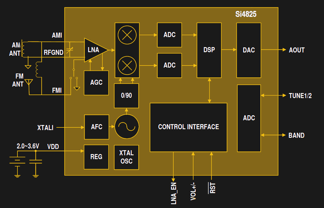
There’s not much to a radio using one of these chips.
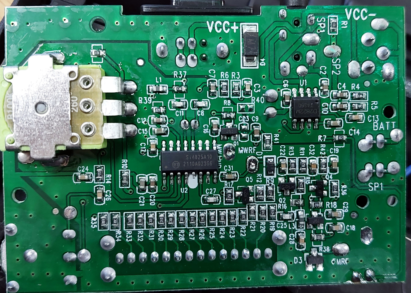
Opening it up, and it’s immediately obvious how simple the DSP chip makes a radio like this. Where once you’d have seen a board covered in analogue circuitry taking up most of the space, now aside from the AM ferrite rod antenna there’s a board about a third the size of the case, behind the tuning display. Carefully lifting this up reveals the circuitry, all surface-mount, with a Silicon Labs Si4825 single-chip DSP radio, and a Shaoxing Silicore D2882 audio amplifier being the only integrated circuits.
How Does It Compare To Older Cheap Radios?
It seems crazy to give an SDR an analogue interface using an ADC, but you can’t deny it works.
The Silicon Labs single-chip radios are nothing new, having been on the market for over a decade. They come in a wide variety of versions for different applications and control methods, with the Si4825 being one of the lower-end versions. In keeping with its traditional analogue interface it doesn’t have any digital controls, instead it achieves both tuning and band switching by means of voltage. A switched voltage divider selects the band, while a variable resistor serves as the tuning control. Some of the higher-spec chips in the series allow the insertion of DSP code to demodulate for example SSB signals, but this one remains firmly stuck with AM, and FM on the two VHF bands. Inserting some batteries and turning it on, and there were the usual dial-full of FM stations. The real action though lies in the shortwave bands, so that was where I headed next. And immediately I had in my headphones a world of stations, and while the shortwave bands have seen a decline since I first listened to them back in the 1980s, there were still enough for me to quickly identify stations from the far east, north America, the Arabic-speaking world, and from eastern Europe.
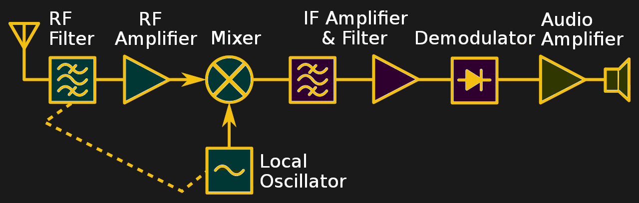
Compare this traditional receiver with the SDR block diagram above. Chetvorno, CC0.
When evaluating a small portable shortwave radio like this one it’s important to understand a little about how such radios have traditionally worked. My other older cheap radio with a few shortwave bands is a more conventional model, it has a tuning capacitor that controls both an input tuned circuit and an oscillator. The oscillator is set 455 kHz away from the desired station, and the signal from the antenna is mixed with it to create a so-called intermediate frequency, the difference between the two at 455 kHz. This is then fed into an IF amplifier tuned to 455 kHz from which the audio can be demodulated.
It has two major shortcomings, first that 455 kHz isn’t enough distance from the receive frequency in a cheap shortwave radio, and second that the bandwidth of that 455 kHz amplifier is quite wide. The first leaves the possibility of receiving whatever is on the sum of the oscillator and 455 kHz alongside its difference, while the second sets the slice of spectrum that you are listening wide enough that more than one station can be heard at once. More expensive traditional receivers like my workhorse 1980s Lowe solve this by using a much larger frequency difference than 455 kHz and some expensive filter components to reduce that bandwidth, but you would certainly find neither in a ten dollar radio. The experience of short wave listening on a very cheap radio has thus always been rather dismal. Tuning is difficult, and there is lots of interference and breakthrough from other stations.
How Good is It And Should You Buy It?
A radio based on one of these Silicon Labs chips immediately solves both of the problems from the previous paragraph due to its software-defined architecture: it has no IF offset to worry about, and it replaces the need for those expensive filters by means of signal processing in its software. Thus the effect is much more similar to that of a receiver with one of those expensive IF filters: there’s little or no breakthrough from all those adjacent stations, and tuning becomes much easier. It also seems as though the demodulator is better than its analogue equivalent, returning even weak signals in a much clearer form. How much of this is my imagination and how much DSP tricks I can’t tell you, but the radio certainly delivers.
To sum up the D-219 then, it’s a good little radio that gives good results for a pocket-money price, and I can see why the SWL community are rather excited about it. It will never equal a high-end general coverage receiver with a well-implemented antenna array and even the Silicon Labs SDR chip is not new, but for the price of a couple of pints of beer it’s a no-brainer and a diamond in the rough.
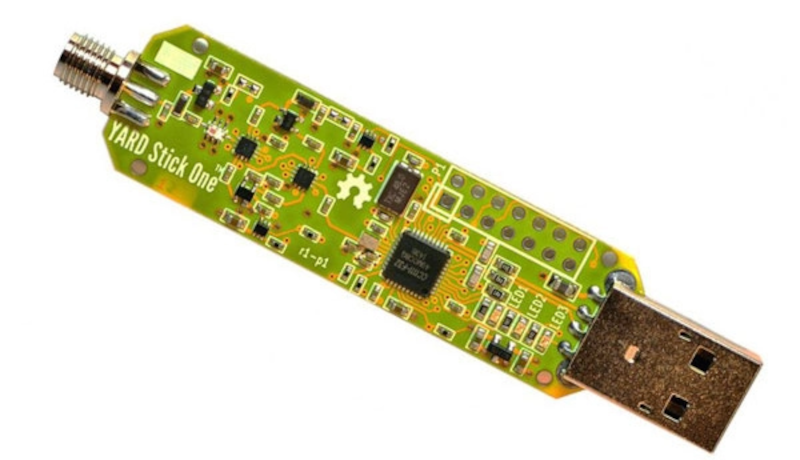
When it comes to SDR, you can usually find cheap products that receive and expensive products that can also transmit. The YARD Stick One bucks that trend. It can send and receive from 300 MHz to 928 MHz, thanks to the onboard TI CC1111 chip. [Wim Ton] on Elektor put the device through its paces. While the frequency range isn’t as broad as some devices, the price is right at about $99. YARD, by the way, stands for Yet Another RF Dongle.
The frequency range isn’t as cut and dry as it might seem. According to the product’s home page: “official operating frequencies: 300 MHz – 348 MHz, 391 MHz – 464 MHz, and 782 MHz – 928 MHz; unofficial operating frequencies: 281 MHz – 361 MHz, 378 MHz – 481 MHz, and 749 MHz – 962 MHz.” The unofficial operating frequencies are not supported by the chip but appear to work in practice.
The device is made for data applications, and the support software is a Python-based interface that abstracts most of what you want to do. You can directly access the device registers if you need more control.
The YARD stick isn’t great as a generic receiver, but as the review points out, you can use it as a transmitter and then grab a cheaper dongle to use as a receiver if you need more capability. The total system cost will still be less than other solutions.
Ultimately, though, [Wim] was less than impressed. Issues with the software and limited documentation didn’t help. But the fact that the CC1111 isn’t meant for general-purpose radio use makes it difficult to put into many projects where you could use an SDR transmitter. A lot of processing happens on the chip which is fine if you know what you want to send and receive ahead of time and the chip supports what you want to do. But for randomly probing and receiving RF, you don’t always have either of those luxuries.
We like the Pluto SDR, which is fairly inexpensive and can transmit. Lime SDR seems to be another popular choice.
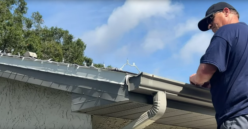
For all their supposed benefits, homeowner’s associations (HOAs) have a reputation of quickly turning otherwise quaint neighborhoods into a sort of Stanford prison experiment, as those who get even the slightest amount of power often abuse it. Arbitrary rules and enforcement abound about house color, landscaping, parking, and if you’ve ever operated a radio, antennas. While the FCC (at least as far as the US is concerned) does say that HOAs aren’t permitted to restrict the use of antennas, if you don’t want to get on anyone’s bad side you’ll want to put up an antenna like this one which is disguised as a set of HOA-friendly holiday lights.
For this build, a long wire is hidden along with a strand of otherwise plain-looking lights. While this might seem straightforward at first, there are a few things that need to be changed on the lighting string in order to make both the antenna and the disguise work. First, the leads on each bulb were removed to to prevent any coupling from the antenna into the lighting string. Clipping the leads turns what is essentially a long wire that might resonate with the antenna’s frequency into many short sections of wire which won’t have this problem. This also solves the problem of accidentally illuminating any bulbs when transmitting, as the RF energy from the antenna could otherwise transfer into the lighting string and draw attention from the aforementioned HOA.
Tests of this antenna seemed to show surprising promise while it was on the ground, but when the string and antenna was attached to the roof fascia the performance dropped slightly, presumably because of either the metal drip edge or the gutters. Still, the antenna’s creator [Bob] aka [HOA Ham] had excellent success with this, making clear contacts with other ham radio operators hundreds of miles away. We’ve shared another of [Bob]’s HOA-friendly builds below as well which hides the HF antenna in the roof’s ridge vent, and if you’re looking for other interesting antenna builds take a look at this one which uses a unique transformer to get wide-band performance out of an otherwise short HF antenna.
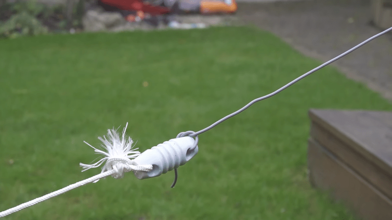
[G3OJV] knows the pain of trying to operate a ham radio transmitter on a small lot. His recent video shows how to put up a workable basic HF antenna in a small backyard. The center of the system is a 49:1 unun. An unun is like a balun, but while a balun goes from balanced line to an unbalanced antenna, the unun has both sides unbalanced. You can see his explanation in the video below.
The tiny hand-size box costs well under $40 or $50 and covers the whole HF band at up to 200 W. The video shows the inside of the box which, as you’d expect, is a toroid with a few turns of wire.
The proposed antenna is an end-fed dipole fed with the unun. These are somewhat controversial with some people swearing they can’t work and others saying they are amazing. We are guessing they may not outperform a perfect antenna system, but we also know that you can have a lot of fun with almost any kind of radiator.
The element is about 33 ft long, but to make it fit, you can bend the antenna to fit your lot. Again, it is probably not optimal, but better than nothing. Erecting a wire antenna like this is easy and just requires some insulators and supporting rope or string. Using thin wire and low-profile rope, you can hide it nearly anywhere.
Does it work? Seems to in the video, at least judging by the SWR. As [G3OJV] says, why not try it before dismissing it?
HF radios often use toroidal transformers and winding them is a rite of passage for many RF hackers. [David Casler, KE0OG] received a question about how they work and answered it in a recent video that you can see below.
Understanding how a conventional transformer works is reasonably simple, but toroids often seem mysterious because the thing that makes them beneficial is also what makes them confusing. The magnetic field for such a transformer is almost totally inside the “doughnut,” which means there is little interaction with the rest of the circuit, and the transformer can be very efficient.
The toroid itself is made of special material. They are usually formed from powdered iron oxide mixed with other metals such as cobalt, copper, nickel, manganese, and zinc bound with some sort of non-conducting binder like an epoxy. Ferrite cores have relatively low permeability, low saturation flux density, and low Curie temperature. The powder also reduces the generation of eddy currents, a source of loss in transformers. Their biggest advantage is their high electrical resistivity, which helps reduce the generation of eddy currents.
If you haven’t worked through how these common little transformers work, [David]’s talk should help you get a grip on them. These aren’t just for RF. You sometimes see them in power supplies that need to be efficient, too. If you are too lazy to wind your own, there’s always help.
NASA’s been recruiting citizen scientists lately, and their latest call is looking for help from ham radio operators. They want you to make and report radio contacts during the 2023 and 2024 North American eclipses. From their website:
Communication is possible due to interactions between our Sun and the ionosphere, the ionized region of the Earth’s atmosphere located roughly 80 to 1000 km overhead. The upcoming eclipses (October 14, 2023, and April 8, 2024) provide unique opportunities to study these interactions. As you and other HamSCI members transmit, receive, and record signals across the radio spectrum during the eclipse, you will create valuable data to test computer models of the ionosphere.
The upcoming eclipses are in October of this year and in April 2024, so you have some time to get your station in order. According to NASA, “It will be a fun, friendly event with a competitive element.” So if you like science, space, or contesting, it sounds like you’ll be interested. Right now, the big event is the Solar Eclipse QSO Party. There will also be a signal spotting challenge and some measurements of WWV, CHU, AM broadcast stations, and measurements of the ionosphere height. There will also be some sort of very low-frequency event. Details on many of these events are still pending.
Hams, of course, have a long history of experimenting with space. They routinely bounce signals off the moon. They also let radio signals bounce off the trails of ionized gas behind meteors using special computer programs.