Bruteforcing Accidental Antenna Designs

Antenna design is often referred to as a black art or witchcraft, even by those experienced in the space. To that end, [Janne] wondered—could years of honed skill be replaced by bruteforcing the problem with the aid of some GPUs? Iterative experiments ensued.

[Janne]’s experience in antenna design was virtually non-existent prior to starting, having a VNA on hand but no other knowledge of the craft. Formerly, this was worked around by simply copying vendor reference designs when putting antennas on PCBs. However, knowing that sometimes a need for something specific arises, they wanted a tool that could help in these regards.

The root of the project came from a research paper using an FDTD tool running on GPUs to inversely design photonic nanostructures. Since light is just another form of radio frequency energy, [Janne] realized this could be tweaked into service as an RF antenna design tool. The core simulation engine of the FDTD tool, along with its gradient solver, were hammered into working as an antenna simulator, with [Janne] using LLMs to also tack on a validation system using openEMS, an open-source electromagnetic field solver. The aim was to ensure the results had some validity to real-world physics, particularly important given [Janne] left most of the coding up to large language models. A reward function development system was then implemented to create antenna designs, rank them on fitness, and then iterate further.

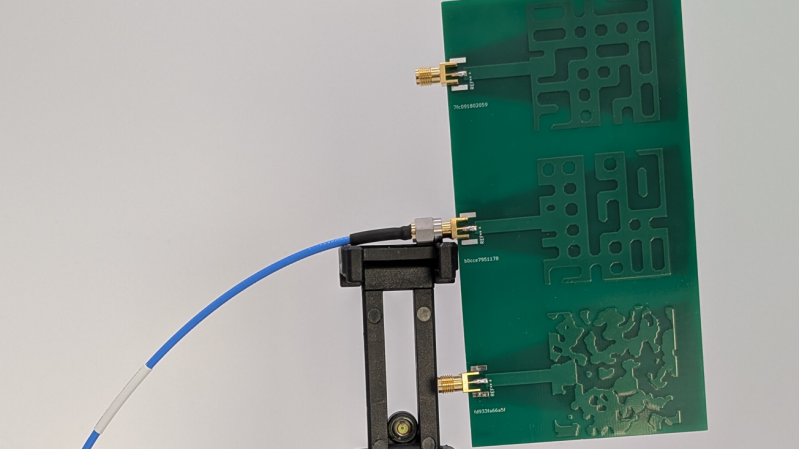
The designs produced by this arcane system are… a little odd, and perhaps not what a human might have created. They also didn’t particularly impress in the performance stakes when [Janne] produced a few on real PCBs. However, they do more-or-less line up with their predicted modelled performance, which was promising. Code is on Github if you want to dive into experimenting yourself. Experienced hands may like to explore the nitty gritty details to see if the LLMs got the basics right.

We’ve featured similar “evolutionary” techniques before, including one project that aimed to develop a radio. If you’ve found ways to creatively generate functional hardware from boatloads of mathematics, be sure to let us know on the tipsline!

A Basic Guide To Shielding

[GreatScott] has recently been tinkering in the world of radio frequency emissions, going so far as to put their own designs in a proper test chamber to determine whether they meet contemporary standards for noise output. This led them to explore the concept of shielding, and how a bit of well-placed metal can make all the difference in this regard.

The video focuses on three common types of shielding—absorber sheets, shielding tapes, and shielding cabinets. A wide variety of electronic devices use one or more of these types of shielding. [GreatScott] shows off their basic effectiveness by putting various types of shielding in between a noise source and a near-field probe hooked up to a receiver. Just placing a bit of conductive material in between the two can cut down on noise significantly. Then, a software defined radio (SDR) was busted out for some more serious analysis. [GreatScott] shows how Faraday cages (or simple shielding cabinets] can be used to crush down spurious RF outputs to almost nothing, and how his noisy buck-boost designs can be quieted down with the use of the right absorber sheets that deal well with the problematic frequencies in question. The ultimate upshot of the tests is that higher frequencies respond best to conductive shielding that is well enclosed, while lower frequency noise benefits from more absorptive shielding materials with the right permeability for the job.

Shielding design can be a complex topic that you probably won’t master in a ten minute YouTube video, but this content is a great primer if you’re new to the topic. We’ve covered the topic before, too, particularly on how a bit of DIY shielding can really aid a cheap SDR’s performance. Video after the break.


Restoring The Soul Of A 1940s Radio

Although we do often see projects that take antiques and replace some or all of their components with modern equipment, we can also sympathize with the view that (when possible and practical) certain antique electronics should be restored rather than gutted. [David] has this inclination for his 1948 GE radio, but there are a few issues with it that prevented a complete, period-correct restoration.

The main (pun intended) issue at the start of this project was safety. The original radio had a chassis that was just as likely as not to become energized, with the only protection being the plastic housing. [David] set up an isolation transformer with a modern polarized power cable to help solve this issue, and then got to work replacing ancient capacitors. With a few other minor issues squared away this is all it took to get the radio working to receive AM radio, and he also was able to make a small modification to allow the radio to accept audio via a 3.5mm jack as well.

However, [David] also has the view that a period-correct AM transmission should accompany this radio as well and set about with the second bit of this project. It’s an adaptation of a project called FieldStation42 originally meant to replicate the experience of cable TV, but [Shane], the project’s creator, helped [David] get it set up for audio as well. A notable feature of this system is that when the user tunes away from one station, it isn’t simply paused, but instead allowed to continue playing as if real time is passing in the simulated radio world.

Although there are a few modern conveniences here for safety and for period-correct immersion, we think this project really hits the nail on the head for preserving everything possible while not rolling the dice with 40s-era safety standards. There’s also a GitHub page with some more info that [David] hopes to add to in the near future. This restoration of a radio only one year newer has a similar feel, and there are also guides for a more broad category of radio restorations as well.