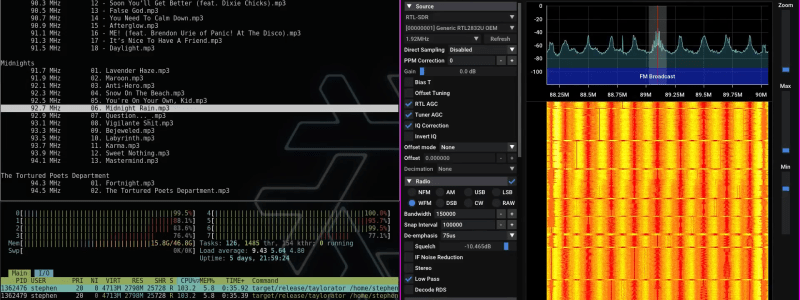
[Stephen] recently wrote in to share his experiments with using the LimeSDR mini to conduct a bit of piracy on the airwaves, and though we can’t immediately think of a legitimate application for spamming the full FM broadcast band simultaneously, we can’t help but be fascinated by the technique. Called the Taylorator, as it was originally intended to carpet bomb the dial with the collected works of Taylor Swift on every channel, the code makes for some interesting reading if you’re interested in the transmission-side of software defined radio (SDR).
The write-up talks about the logistics of FM modulation, and how quickly the computational demands stack up when you’re trying to push out 100 different audio streams at once. It takes a desktop-class CPU to pull it off in real-time, and eats up nearly 4 GB of RAM.
You could use this project to play a different episode of the Hackaday Podcast on every FM channel at once, but we wouldn’t recommend it. As [Stephen] touches on at the end of the post, this is almost certainly illegal no matter where you happen to live. That said, if you keep the power low enough so as not to broadcast anything beyond your home lab, it’s unlikely anyone will ever find out.
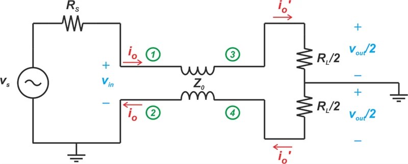
Even before entering the mystical realms of UHF design, radio frequency (RF) circuits come with a whole range of fun design aspects as well. A case in point can be found in transmission line transformers, which are commonly used in RF power amplifiers, with the Guanella transformer (balun) being one example. Allowing balanced and unbalanced (hence ‘balun’) systems to interface without issues, they’re both very simple and very complex. This type of transformer and its various uses is explained in a video by [FesZ Electronics], and also the subject of an article by [Dr. Steve Arar] as part of a larger series, the latter of which is recommended to start with you’re not familiar with RF circuitry.
Transmission line transformers are similar to regular transformers, except that the former relies on transmission line action to transfer energy rather than magnetic flux and provides no DC isolation. The Guanella balun transformer was originally described by Gustav Guanella in 1944. Beyond the 1:1 balun other configurations are also possible, which [Dr. Arar] describes in a follow-up article, and which are also covered in the [FesZ] video, alongside the explanation of another use of Guanella transformers: as an impedance transformer. This shows just how flexible transformers are once you can wrap your mind around the theory.
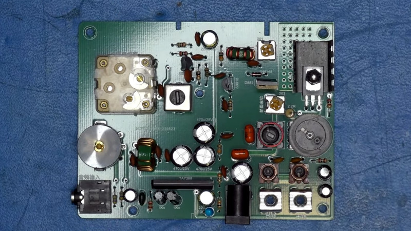
The chances are that many of you will have made an FM “bug” style transmitter, a simple one-transistor oscillator usually driven by a small electret microphone. It’s also relatively straightforward to do the same for AM, and if you take a look through AliExpress you’ll find some modules which do just that. [Doz Television Workshop] has one, and he’s treated us to a thorough run-down of its design before addressing some of its shortcomings.
An AM transmitter is simple enough, in this case an oscillator and buffer driving a class C power amplifier. The modulation is applied by a transistor in series with the power amp, driven from an audio amplifier. Some attention has gone into the design of this one, with a proper output filter and plenty of room for tweaking to achieve proper levels and modulation density. There are some problems though — The modulator transistor is mounted upside down for the heatsink, and the frequency stability leaves something to be desired. [Doz] fixes the heatsink mounting and incorporates a DDS frequency synthesizer with an Arduino for control.
More after the break…
The resulting transmitter is better, but there’s still a problem. The limitations of AM broadcasting demanded both limiting and pre-emphasis, which he applies in software through one of the more powerful Teensy boards. We have to admit we’d have tried to do the job the analogue way, but that’s merely preference.
This board looks to be a good solution for an AM radio collector wishing to use their sets in an age of declining AM transmission. It should be legal under Part 15 for Americans, but as he points out it’s not for Brits. We suspect such a low-powered device wouldn’t attract adverse attention though. The video is below the break.
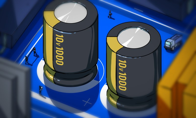
Everyone knows that the perfect capacitor to decouple the power rails around ICs is a 100 nF ceramic capacitor or equivalent, yet where does this ‘fact’ come from and is it even correct? These are the questions that [Graham] set out to answer once and for all. He starts with an in-depth exploration of the decoupling capacitor (and related) theory. [Graham] then dives into the way that power delivery is affected by the inherent resistance, capacitance, and inductance of traces. This is the problem that decoupling capacitors are supposed to solve.
Effectively, the decoupling capacitor provides a low-impedance path at high frequencies and a high-impedance path at low frequencies. Ideally, a larger value capacitor would be better, but since this is the real world and capacitors have ESL and ESR parameters, we get to look at impedance graphs. This is the part where we can see exactly what decoupling effect everyone’s favorite 100 nano-farad capacitors have, which as it turns out is pretty miserable.
Meanwhile, a 1 µF (ceramic) capacitor will have much better performance, as shown with impedance graphs for MLCC capacitors. As a rule of thumb, a single large decoupling capacitor is better, while two MLCC side-by-side can worsen noise. Naturally, one has to keep in mind that although ‘more capacity is better for decoupling’, there is still such a thing as ‘inrush current’ so don’t go too crazy with putting 1,000 µF decoupling capacitors everywhere.
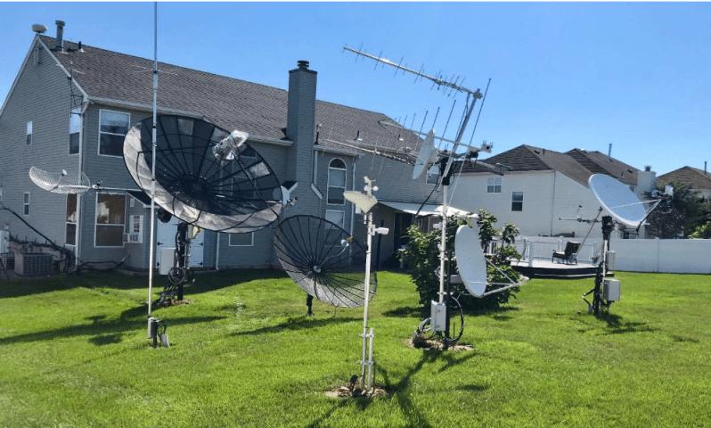
Not too far away from where this is being written is one of Uncle Sam’s NATO outposts, a satellite earth station for their comms system. Its most prominent feature is a radome, a huge golf-ball-like structure visible for miles, that protects a large parabolic antenna from the British weather. It makes sense not just for a superpower to protect its antennas from the elements, and [saveitforparts] is doing the same with a geodesic dome for his radio telescope experiments. But what effect does it have on the received signal? He’s made a video to investigate.
The US military radome is likely constructed of special RF-transparent materials, but this smaller version has a fibreglass skin and an aluminium frame. When he compares internal and external sky scans made with a small motorised satellite TV antenna he finds that the TV satellites are just as strong, but that the noise floor is higher and the frame is visible in the scan. It’s particularly obvious with such small dish, and his planned larger array should improve matters.
We would be curious to know whether an offset-fed dish constructed to minimise ground noise reaching the LNB, would improve matters further. It’s no surprise that the frame doesn’t impede the TV satellites though, as it is many wavelengths wide at that frequency. The video is below the break, and meanwhile, we featured the antenna he’s using here in 2023.
One of the more popular activities in the ham radio world is DXing, which is attempting to communicate with radio stations as far away as possible. There are some feats that will earn some major credibility in this arena, like two-way communication with Antarctica with only a few watts of power, long-path communication around the globe, or even bouncing a signal off the moon and back to a faraway point on Earth. But these modes all have one thing in common: they’re communicating with someone who’s also presumably on the same planet. Barring extraterrestrial contact, if you want to step up your DX game you’ll want to try to contact some of our deep-space probes (PDF warning).
[David Prutchi] aka [N2QG] has been doing this for a number of years now and has a wealth of knowledge and experience to share. He’s using both a 3.2 meter dish and a 1.2 meter dish for probing deep space, as well as some custom feed horns and other antennas to mount to them. Generally these signals are incredibly small since they travel a long way through deep space, so some amplification of the received signals is also needed. Not only that, but since planets and satellites are all moving with respect to each other, some sort of tracking system is needed to actively point the dish in the correct direction.
With all of that taken care of, it’s time to see what sort of signals are coming in. Compared to NASA’s 70-meter antennas used to communicate with deep space, some signals received on smaller dishes like these will only see the carrier wave. This was the case when an amateur radio group used an old radio telescope to detect one of the Voyager signals recently. But there are a few cases where [David] was able to actually receive data and demodulate it, so it’s not always carrier-only. If you’re sitting on an old satellite TV dish like these, we’d certainly recommend pointing it to the sky to see what’s out there. If not, you can always 3D print one.
When it comes to amateur radio, one size definitely does not fit all. That’s especially true with antennas, which need to be just the right size for the band you’re working, lest Very Bad Things happen to your expensive radio. That presents a problem for the ham who wants the option to work whichever band is active, and doubly so if portable operation is desired.
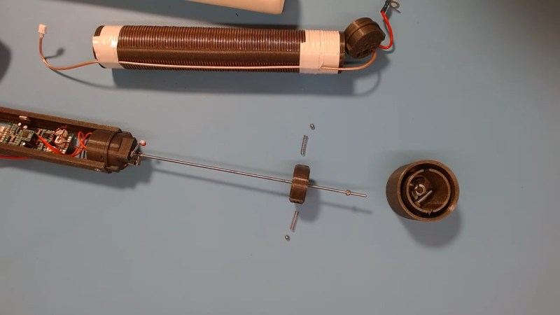
Of course, there are commercial solutions to this problem, but they tend to be expensive. Luckily [Øystein (LB8IJ)] seems to have found a way around that with this low-cost homebrew motorized antenna coil, which is compatible with the Yaesu Automatic Tuning Antenna System. ATAS is supported by several Yaesu transceivers, including the FT-891 which [Øystein] favors for field operations. ATAS sends signals up the feedline to a compatible antenna, which then moves a wiper along a coil to change the electrical length of the antenna, allowing it to resonate on the radio’s current frequency.
The video below details [Øystein]’s implementation of an ATAS-compatible tuning coil, mainly focusing on the mechanical and electrical aspects of the coil itself, which takes up most of the room inside a 50-mm diameter PVC tube. The bore of the air-core coil has a channel that guides a wiper, which moves along the length of the coil thanks to a motor-driven lead screw. [Øystein] put a lot of work into the wiper, to make it both mechanically and electrically robust. He also provides limit switches to make sure the mechanism isn’t over-driven.
There’s not much detail yet on how the control signals are detected, but a future video on that subject is promised. We’re looking forward to that, but in the meantime, the second video below shows [Øystein] using the tuner in the field, with great results.
Full disclosure: ham radio isn’t for everyone, and there are many different facets to it. What appeals to one person might bore another to death. One area of ham radio that has changed a lot in the last few years is more or less local and typically mobile operation on VHF or UHF. Not long ago, hams used HTs (walky-talkies or handi-talkies) or mobile radios via repeaters to talk to each other and — the golden prize back then — make phone calls from their cars. Cell phones have made that much less interesting, but there is still an active community of operators talking on repeaters. However, the traffic has gone digital, the Internet is involved, and people with inexpensive, low-powered radios can talk to each other across the globe. This is nothing new, of course. However, having digital services means that operators with special interests can congregate in what amounts to radio chat rooms organized by region or topic.
There’s a long history of people listening to ham radio conversations with shortwave radios, SDRs, and scanners. But with so much activity now carried on the Internet, you can listen in using nothing more than your web browser or a phone app. I’ll show you how. If you get interested enough, it is easy enough to get your license. You don’t need any Morse code anymore, and a simple Technician class license in the United States is all you need to get going.
A Quick DMR Primer
There are several digital ham networks around and like real networks, you can have different physical transport layers and then build on top of that. For the purposes of this post, I’m going to focus on DMR (digital mobile radio) on the Brandmeister network which is very large and popular ham network. You won’t need a license nor will you need to sign up for anything as long as you are content to just listen.
Here’s how it works: Brandmeister operates a large number of servers worldwide that communicate with each other and provide calling services, including group calls. So, if we set up a Hackaday talk group (fictitious, by the way) on group 1337, interested people could connect to that talk group and have a conversation.
Since we are just going to listen, I’m going to skip some of the details, but the trick is how people get to talk to these networks. In general, there are three ways. The classic way is to use a digital radio to talk to a repeater that is connected to the network. The repeater may have one or more talk groups on all the time, or you might request access to one.
However, another way to connect your radio to a “hotspot” connected to the Internet. That is, more or less, a special form of repeater that is very low power, and you have complete control over it compared to a repeater on some faraway hill. However, if you don’t mind operating using just a computer, you don’t need a radio at all. You simply talk directly to the nearest server, and you are on the network. Some of your audio will go to other computers, and it may go over the airwaves via someone else’s hotspot or repeater.
Talk Groups
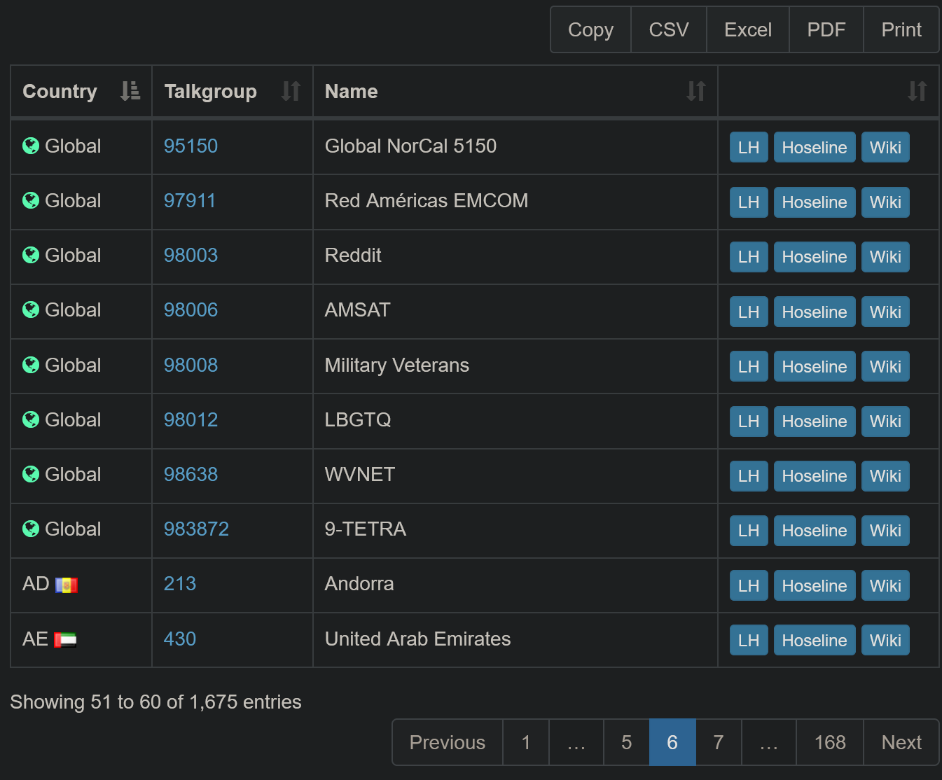
Just a few of the 1,600+ talkgroups available on the network
The Brandmeister website has a lot of info and you don’t need to be logged in to see it. Head over to their site and you’ll see a lot of info including a network map and statistics about repeaters and hotspots. You can get an idea of who has been talking lately by clicking Last Heard link. While this is interesting, it isn’t as interesting as you’d think, because you really want to focus on talk groups, not individual users.
To see a list of all the talk groups on the system, you can click Information and then Talkgroups. You can filter the list and you can also download the dataset in different formats if you want to browse it in a different format.
The hoseline shows you all the activity across the network and lets you listen in, too.
There are three buttons on each row of the database. The LH button shows you the last heard stations for that group. The Wiki button takes you to a Wiki page that, for some groups, has more information about it. But the really interesting button is the one marked Hoseline. You can also open the Hoseline directly which is what I usually do.
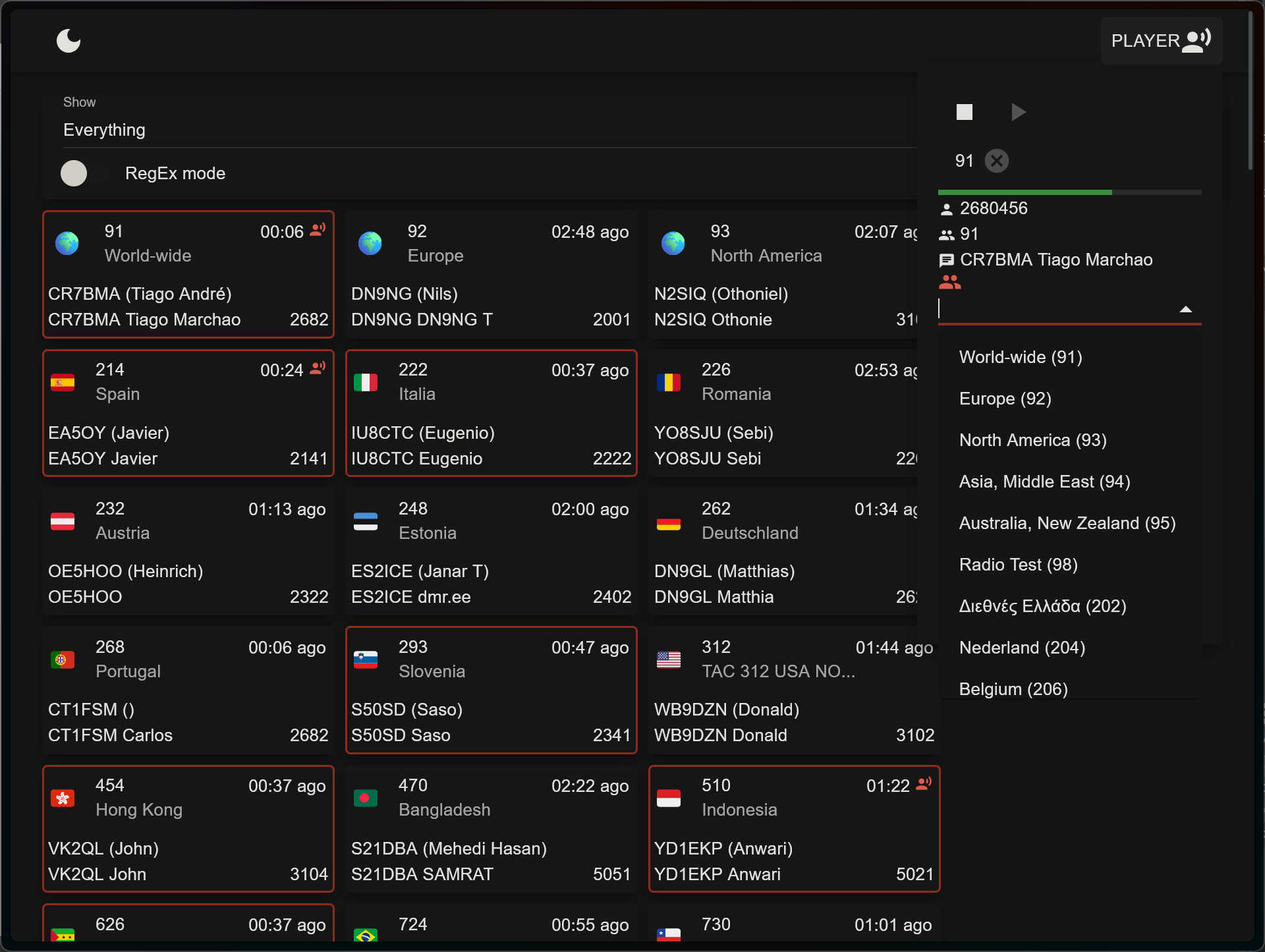
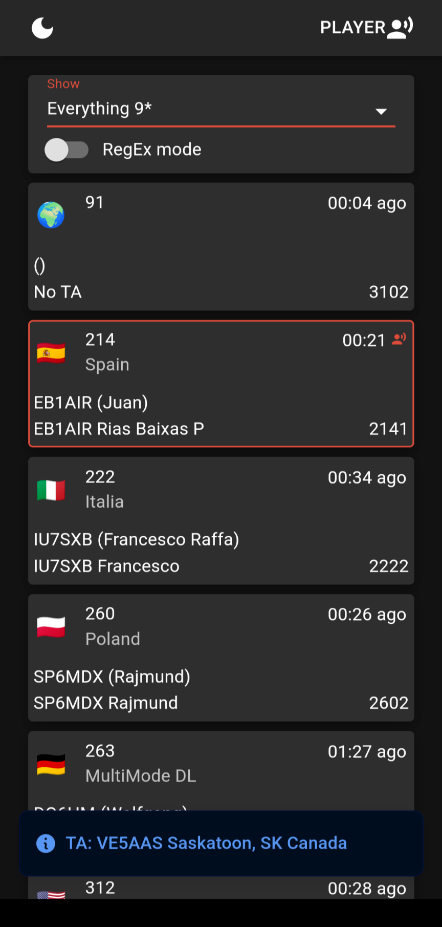
What’s the Hoseline? It shows activity across the network as a bunch of boxes indicating recently active talk groups. Boxes with red lines around them have people actively talking on them. The others have been recently active. It is visually interesting, yes, but that’s not the big selling point.
If you click on a box, you will hear the activity on that talk group. That’s all there is to it.
Overwhelming
There are a lot of talk groups. You can filter at the top left part of the page where it says “Everything.” You’ll have to drop the list down and unselect Everything. Then, you can select any countries or areas you want to follow. If you are brave, you can click RegEx mode and enter regular expressions to match talk group numbers (e.g. ^310.*).
The “Player” button at the top right gives you more control. You can add multiple groups from a list, see information about who is talking, and stop or start the audio.
The hose is available on Android, too.
If you prefer to do your listening mobile, you can also get the hoseline on your Android device. Just install the app, and you’ll find it works the same way.
Finding Something Interesting
Lord Nelson once said, “The greatest difficulty in war is not to win the battle, but to find the enemy.” That’s accurate here, too. Finding an interesting conversation out of all those talk groups is somewhat a needle in a haystack. A quick look around at the talk group lists might help.
The 91 and 93 groups stay busy but generally with short exchanges since they cover a wide area. The USA bridge at 3100 sometimes has traffic, too.
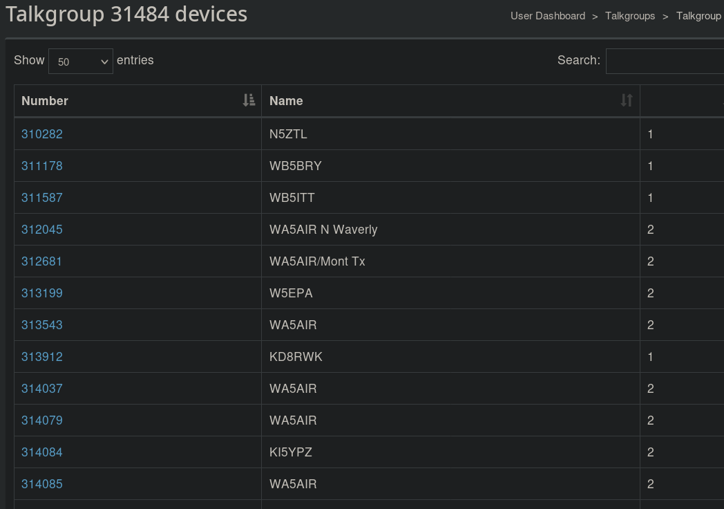
Talk group 31484 (SE Texas) has 66 devices attached, some of which you can see here.
If you look at the group’s listing on the Web, you can click the group number and see what stations are connected to it. Keep in mind, some of these may be repeaters or gateways that could have no one on the other side, or could have dozens of people on the other side. But it can give you an idea if the talkgroup has any users at all.
You can also search the Internet for DMR nets and repeaters. Sometimes, it is interesting to listen to local repeaters. Sometimes, it is fun to listen to repeaters in other places. Want to find out what’s going on at your next vacation spot? Practice your French?
There are many other similar networks, but they may not have a way to listen that doesn’t require some software, registration, or licenses. There’s plenty on Brandmeister to keep you busy. If you worry about people listening in, that’s no different than regular radio has been since the beginning.
You can always get your ham license and join in. Even without a radio, there are ways to talk on the network. [Dan Maloney] has advice for getting your “ticket.” It is easier than you think, and you can do a lot more with a license, including talking through satellites, sending TV signals over the air, and bouncing signals of meteors or the moon. If you want to listen to more traditional ham radio in your browser, try a Web-based SDR.
These days, anything with copper in it is expensive. If you doubt that, a walk into any Home Depot electrical department, where the wire is locked up tighter than Fort Knox, will prove otherwise. Coaxial cable is a particularly expensive species, which is a pity for hams and other radio enthusiasts since it’s the only thing we can use for antenna feedlines.
Or is it? [Steve (VE6WZ)] has found a way to use ordinary Cat 6 Ethernet cable for antenna feed lines that seems pretty clever. As he points out, Ethernet cables are designed to handle frequencies that coincide nicely with most of the interesting amateur radio bands, and their insertion losses are acceptably low, especially for Cat 6 cable. The twisted pairs are also a balanced system that’s good at rejecting common mode noise. Cat 6 cable also has four pairs of conductors, allowing you to feed multiple antennas with one cable, or to distribute power to amplifiers and switches along with antenna feeds.
The downside? Cat6 conductor pairs have a characteristic impedance of around 100 ohms, which isn’t a match for the 50-ohm feedline impedance universally expected by ham radios. Also, the relatively small wires probably aren’t up to the job of carrying much current, limiting their use to feedlines for receive-only antennas. That works for [Steve] since he uses Cat 6 to support his massive Beverage antenna farm (Beverage antennas are non-resonant horizontal antennas that live close to the ground and point in the direction of the signal, rather than broadside to the signal as with a resonant antenna like a dipole.) Each antenna in his farm has a transimpedance amplifier that needs to be powered, plus switching relays so he can turn the correct antennas on for the signals he wants to receive. He describes the amps in detail in the video below, along with the custom impedance-matching transformers he uses and the combining gear.
Coax will probably still be the cable of choice for most feedline applications, but it’s nice to know there are alternatives. And who knows—if you stick to QRP work, maybe Cat 6 could even be used for transmitting.
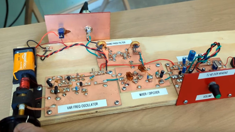
A couple of years ago one of the Hackaday Prize finalists was a project to take highschoolers through building a direct conversion radio receiver for the 40 metre amateur band. It was originated by the SolderSmoke podcast, and we’re pleased to see that they’ve recently put up an overview video taking the viewer through the whole project in detail.
It’s a modular design, with all the constituent building blocks broken out into separate boards on which the circuitry is built Manhattan style. Direct conversion receivers are pretty simple, so that leaves us with only four modules for oscillator, bandpass filter, mixer, and audio amplifier. We particularly like that it’s permeability tuned using a brass screw and an inductor, to make up for the once-ubiquitous variable capacitors now being largely a thing of the past.
A point that resonated was that most radio amateurs never make something like this. Arguments can be made about off-the-shelf rigs and chequebook amateurs, but we’d like to suggest that everyone can benefit from a feel for analogue circuitry even if they rarely have a need for a little receiver like this one. We like this radio, and we hope you will too after seeing the video below the break.