So far in this series, we’ve covered the absolute basics of getting on the air as a radio amateur – getting licensed, and getting a transceiver. Both have been very low-cost exercises, at least in terms of wallet impact. Passing the test is only a matter of spending the time to study and perhaps shelling out a nominal fee, and a handy-talkie transceiver for the 2-meter and 70-centimeter ham bands can be had for well under $50. If you’re playing along at home, you haven’t really invested much yet.
The total won’t go up much this week, if at all. This time we’re going to talk about what to actually do with your new privileges. The first step for most Technician-class amateur radio operators is checking out the local repeaters, most of which are set up exactly for the bands that Techs have access to. We’ll cover what exactly repeaters are, what they’re used for, and how to go about keying up for the first time to talk to your fellow hams.
Could You Repeat That?
Time to face some cold, hard facts about amateur radio: that spiffy new Baofeng radio I recommended last time as a great starter radio is actually pretty lame. That fact has little to do with the mere $25 you spent on it, or $40 if you opted to upgrade the antenna. It’s a simple consequence of physics: a radio that transmits at 5 watts will only have so much range on the VHF band, and even less on UHF. Even if you buy a more powerful HT, or invest in a mobile or base-station rig running 50 or 100 watts, the plain fact is that direct radio-to-radio contacts on the same frequency, or simplex contacts, are difficult on VHF and UHF because those bands are really best for line of sight (LOS) use.
That’s not to say that hams don’t use their VHF and UHF rigs for simplex communications, of course. Many hams like to see just how far they can push their signals on these bands, building big Yagi antennas and finding mountain peaks to operate from. But for general use around town, most hams rely on repeaters to extend the area they can communicate over. Repeaters are simply transceivers set up to receive signals on one frequency and transmit them on another at the same time, with the help of a device called a duplexer. This simultaneous reception and transmission gives rise to the term duplex communications, the general term for operating on a repeater.
Repeater usually transmit at a much higher power than an HT or even a mobile rig can manage, and they usually have the advantage of being located on a mountaintop or some other elevated place to gain the furthest possible radio horizon as possible. This arrangement vastly increases the area that you can cover with your tiny HT. Depending on how the repeater is sited and what sort of antenna it has, you may be able to cover hundreds of square miles, as opposed to perhaps a few miles radius under ideal conditions, or a few blocks in the typical urban or suburban setting with lots of clutter from buildings and trees. What’s more, some repeaters are linked to other repeaters either through backhaul connections, often via the Internet but also sometimes through powerful LOS microwave links. In these systems it’s possible to use a puny HT to talk to another ham over hundreds or even thousands of miles. It’s actually pretty cool.
Welcome to the Machine
So where are these repeaters, and how do you start working them? The first question is easy to answer: they’re everywhere. Look at any tall building, mountaintop antenna farm, or municipal water tank, and chances are pretty good there’s a ham repeater there. But being able to work them means you need to know exactly where they are, to be sure you’re in range of the repeater, or “the machine” as hams often refer to it, as well as the frequencies it operates on.
Luckily, there are online guides to help with that chore. RepeaterBook.com is usually the first place hams go to find machines in the area. There you can search by state, county, or city, or even via a map, and find what repeaters are available. They’ve even got a handy road search, so you can get all the repeaters listed as within range of a particular highway; that’s really handy for road-trip planning. Here’s what comes up for VHF and UHF repeaters when I search within 25 miles of my location, or QTH:
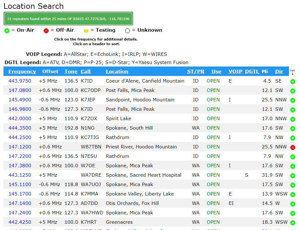
The first thing you’ll notice is that several machines at different sites have the same callsign. For example, K7ID runs a UHF repeater on Canfield Mountain and a VHF machine on Mica Peak. Both are LOS to me, and I can easily hit them with an HT. The frequency listed in the first column is the transmit frequency of the repeater. Your HT will need to be set to this frequency to hear what’s being said. Your radio will also need to be programmed for the correct tone, listed in the third column. That tone is an audio frequency signal known by a number of different trade names, but generically as continuous tone-coded squelch system (CTCSS). Your radio is capable of adding this sub-audible tone to your transmission; the repeater will only “open up” to transmissions that are correctly coded. Some repeaters have no tone coding, others have different tones for receive and transmit. When doubt, try to find out who runs the machine – most, but not all, are run by a ham radio club – and see if you can look up instructions on the web.
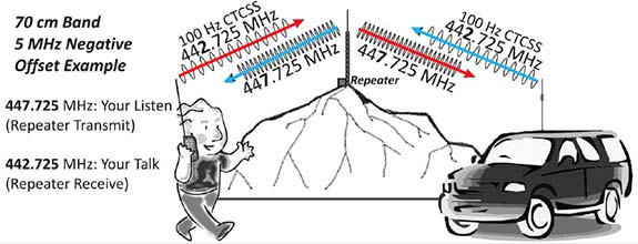
The offset shown in the second column is perhaps the most important bit of information. Recall that repeaters transmit and receive on different frequencies, and that they’re listed by their transmit frequency. The offset tells you what the repeater’s input frequency is, which is the frequency your radio will need to be set to transmit on. For example, the machine I most often used is the K7ID machine on Mica Peak. It’s at 146.980 and shows an offset of -0.6 MHz. That means that my radio has to be set to 146.380 MHz transmission frequency. VHF repeaters are usually 0.6 MHz, but could be plus or minus depending on which part of the VHF band they’re in. UHF repeaters usually have +5 MHz offsets.
Note: I’m not going to cover programming your radio, because there are plenty of guides online that do a better job than I can. DuckDuckGo is your friend.
Casting the Net
Once you’ve found your local repeaters and programmed your radio, it’s time to get on the air. My advice is to spend the first few days just listening to one or more repeaters. Activity levels vary – some machines are hopping all day, and some are barely used except during the typical commuting hours. When you hear a conversation, try to get a feeling for the culture of the repeater. Every group of hams has a culture, and as we discussed in the first installment of the series, it’s not always a healthy culture. My local repeater belongs to the Kootenai Amateur Radio Society, as friendly and as inviting a group of people as I’ve ever heard on the air. After listening to them chat for a few weeks, I was more than ready to reach out to them.
But first, a word about kerchunking. If you want to know if you’re in range of a repeater, you can test it out. Most repeaters have a “squelch tail” that keeps the repeater on the air for several seconds before going back to sleep, and this can be used to check if you’re in range. Some repeaters even identify themselves, either with a synthesized voice or Morse code when they “wake up”. So you might want to ping the repeater.
Kerchunking, or transmitting into a repeater without identifying yourself, is one of those bad habits that everyone seems to have. But FCC part 97 rules, which cover the amateur radio service, require operators to transmit their call sign when they start a transmission. So don’t kerchunk; a simple identification like “This is KC1DJT testing and clear” will suffice. Nobody is likely to take that as an invitation to chat, but they might give you a reception report.
Once you’re feeling confident enough, try making a contact. I highly recommend checking out the local traffic networks. Hams pride themselves on having the skills and equipment to communicate in an emergency, but that means little without practice to keep everything sharp. Nets allow hams to practice message passing skills and to test their gear on a regular basis. My local group has a network check-in every night that follows a standard script and usually attracts about 30 check-ins. Here’s a sample from a recent check-in:
I’ve become a regular on this net and a few others, mainly because I want to practice, but also to get over my mic shyness. There’s another reason too – I want people to recognize my voice and callsign. If there ever is an emergency in my area, I feel like it’ll be easier to pitch in or to get help if I need it if people hear a familiar voice.
Next Time
Over the next few installments, we’re finally going to get to what I think ham radio is all about at its core: homebrewing. We’ll be building a few simple projects to make that cheap HT a little better, and also build a few tools to help run the shack a little more efficiently.