The modern ham radio shack can take many forms. Some are shrines the “boat anchor” radios of old, named for their considerable weight. Others are simply a small, unassuming software-defined radio (SDR) hooked up to a laptop. Nowadays, many shacks fall somewhere in the middle. It’s not uncommon to find a sleek Icom IC-7300 sitting atop an ancient Hallicrafters SX-115 (which sounds suspiciously like the author’s setup). When a ham wants to work a digital mode such as FT-8, they will undoubtedly reach for a newer radio complete with USB (Universal Serial Bus in this case, not Upper Sideband) rig control — but what if the newest piece of equipment they have is a thirty-year-old Kenwood?
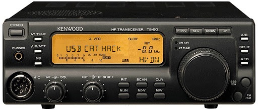
If that sounds like you, then fear not because [Steve Bossert] has you covered. He took his trusty Kenwood TS-50, a classic radio from 1993 whose most advanced feature is fuzzy logic, and upgraded it with USB (again, the serial bus) control.
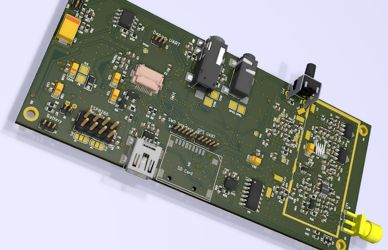
When Kenwood designed the TS-50, they had computer control in mind. There’s a hidden port on the bottom of the unit which reveals a connector that mates with Kenwood’s proprietary (and expensive) set of serial control cables. Thankfully, the engineers over at Kenwood decided to use UART for PC communication, so slapping a USB port in the radio’s case isn’t as daunting as it may sound. [Steve] picked up a CP2104 USB-TTL UART Serial Adapter and wired it up to the radio’s control port. After a bit of drilling, screwing, and gluing, the radio had an upgraded (and non-proprietary!) interface compatible with the ever-popular hamlib. While this doesn’t cover all radio control functions, it gets you tuning, which is pretty important. For a fully modern radio experience, [Steve] suggests using the 8-pin mic connector along with an interface such as Rigblaster or Signalink. This adds PTT and audio signal routing.
If you want to try this for yourself, be sure to check out [Steve]’s extremely well-documented writeup. You could even take this a step further and control your TS-50 from your smartphone with this HTML5 interface we saw a few months back.
Many ham radio operators now live where installing an outdoor antenna is all but impossible. It seems that homeowner’s associations are on the lookout for the non-conformity of the dreaded ham radio antenna. [Peter] can sympathize, and has a solution based on lessons of spycraft from the cold war.
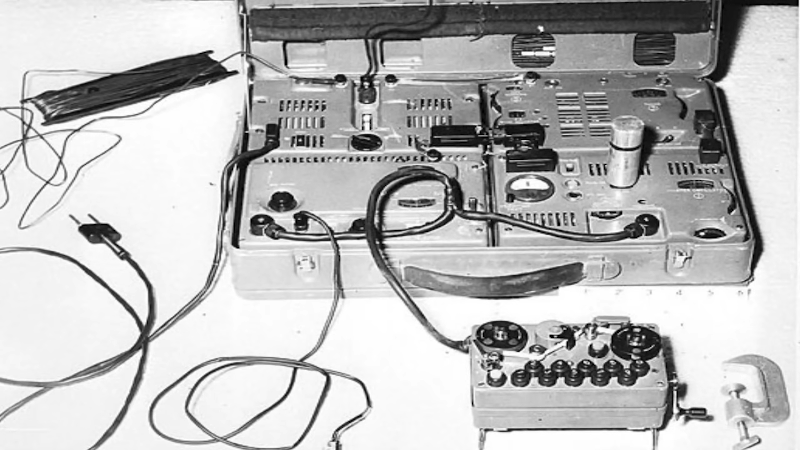
[Peter] points out that spies like the [Krogers] needed to report British Navy secrets like the plans for a nuclear boomer sub to Russia but didn’t want to attract the attention of their neighbors. In this case, the transmitter itself was so well-hidden that it took MI5 nine days to find the first of them. Clearly, then, there wasn’t a giant antenna on the roof. If there had been, the authorities could simply follow the feedline to find the radio. A concealed spy antenna might be just the ticket for a deed-restricted ham radio station.
The antenna the [Kroger’s] used was a 22-meter wire in the attic of their home. Keep in mind, the old tube transmitters were less finicky about SWR and by adjusting the loading circuits, you could transmit into almost anything. Paradoxically, older houses work better with indoor antennas because they lack things like solar cell panels, radiant barriers, and metallic insulation.
Like many people, [Peter] likes loop antennas for indoor use. He also shows other types of indoor antennas. They probably won’t do as much good as a proper outdoor antenna, but you can make quite a few contacts with some skill, some luck, and good propagation. [Peter] has some period spy radios, which are always interesting to see. By today’s standards, they aren’t especially small, but for their day they are positively tiny. Video after the break.
If you think spy radios were small then, you should see what you can do now. Then again, some of the most famous cold war spy radios didn’t have any obvious antenna or even required power.
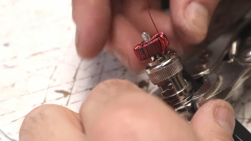
[K6ARK] likes to operate portable, so he puts together very lightweight antennas. One of his latest uses tiny toroids and SMD capacitors to form trap elements. You can see the construction of it in the video below.
You usually think of toroid winding as something you do when building transmitters or receivers, especially small ones like these. We presume the antenna is best for QRP (low power) operation since the tiny core would saturate pretty quickly at higher power. Exactly how much power you should pass through an FT50-43 core depends on the exact application, but we’ve seen numbers around 5 watts.
The SMD capacitors mount right inside a hacked up BNC connector. That makes for a very compact construction at the expense of a little fine work with a soldering iron while building. There is more construction detail on similar traps in a second video that you can see below.
The availability of antenna analyzer equipment makes projects like this easier. The concept of end-fed halfwave has its detractors and proponents. [AA5TB] has a page that explains a bit about the theories surrounding the antenna. Regardless, [K6ARK] says he’s worked the world on this type of antenna and many people swear by them.
Not a ham yet? [Dan Malone] wants you to invest $50 and change that. We suspect, though, you’ll be happier with more wire in the air.
Hiermee nodigen we je uit voor de gezamenlijke lezing van VERON en VRZA Zuid Limburg. De omstandigheden lenen zich nog niet voor een fysieke bijeenkomst, daarom starten we op woensdag 18 november 2020 met een lezing via internet m.b.v. Jitsi.
Deze avond zullen Jan PA0SIM en Loek PE0MJX ons alles gaan vertellen over de door hun gerealiseerde Web-SDR in Maasbree. Waarom een WebSDR ? Hoe zoek je een geschikte locatie en hoe installeer je een WebSDR ? Welke antenne en ontvangers worden gebruikt ? Wat betekent het om een WebSDR te configureren? Waarom is het technisch interessant en uitdagend ?
Ten opzichte van een eerder gehouden landelijk RF-Webinar is het verhaal aangepast en geactualiseerd.
– òf ga in de JITSI app op je mobiel: pi3zlb – sluit deze wel aan op de lader i.v.m.het energieverbruik van je mobiel!
Als alles goed gaat kom je dan in het virtueel/digitaal vergaderzaaltje waar we elkaar kunnen treffen. De meeting start om 20 uur, maar het ‘zaaltje’ zal rond 19.45 al open zijn voor mensen die nog wat hulp nodig hebben met de bedieningsinstructies. Het audio van de zondagochtendronde wordt ook gestreamd via https://meet.jit.si/pi3zlb dan is het oom mogelijk om Jitsi te testen.
Graag tijdens de lezing de camera uit laten, en microfoon alleen inschakelen indien je wat wil zeggen.
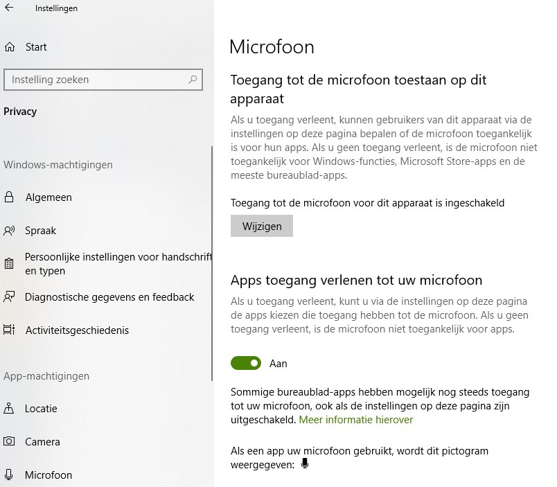
** Wie voor het eerst met jitsi aan de slag gaat, kan mogelijk tegen privacy instellingen op de PC aanlopen. Check bij Instellingen / Privacy dat programma’s de microfoon / camera mogen gebruiken.
We denken hiermee weer een interessant onderwerp te bieden, graag tot ziens dus op woensdag 18 nov om 20.00u
Belangstellenden van buiten de verenigingen zijn welkom.
I suppose most of us have had the experience of going to the mailbox and seeing that telltale package in the white plastic bag, the sign that something has just arrived from China. This happened to me the other day, and like many of you it was one of those times when I puzzled to myself: “I wonder what I bought this time?”
With so many weeks or months between the time of your impulsive click on the “Buy Now” button on AliExpress or eBay and the slow boat from China actually getting the package to your door, it’s easy enough to forget what exactly each package contains. And with the price of goods so low, the tendency to click and forget is all the easier. That’s not necessarily a good thing, but I like surprises as much as the next person, so I was happy to learn that I was now the owner of a tinySA spectrum analyzer. Time for a look at what this little thing can do.
First Impressions
A caveat: I’m by no means an expert on spectrum analyzers. In fact, this is the first time I’ve ever handled one, unless you count using the FFT functions in my digital oscilloscope, which you probably shouldn’t. So there’s probably plenty of room for operator error and misconceptions about what a spectrum analyzer can do in the tests that I ran, but I still think this is valuable as an example of what a tool like this can do in the hands of an enthusiastic newbie.
Anyone familiar with the NanoVNA, a small but full-featured vector network analyzer that we’ve featured a few times on these pages, will see a strong family resemblance between it and the tinySA, both in the hardware and the software. That’s for good reason — the code behind tinySA is a fork off the NanoVNA codebase, and the main developer of NanoVNA, edy555, is a contributor to the tinySA project, which is owned by Erik Kaashoek.
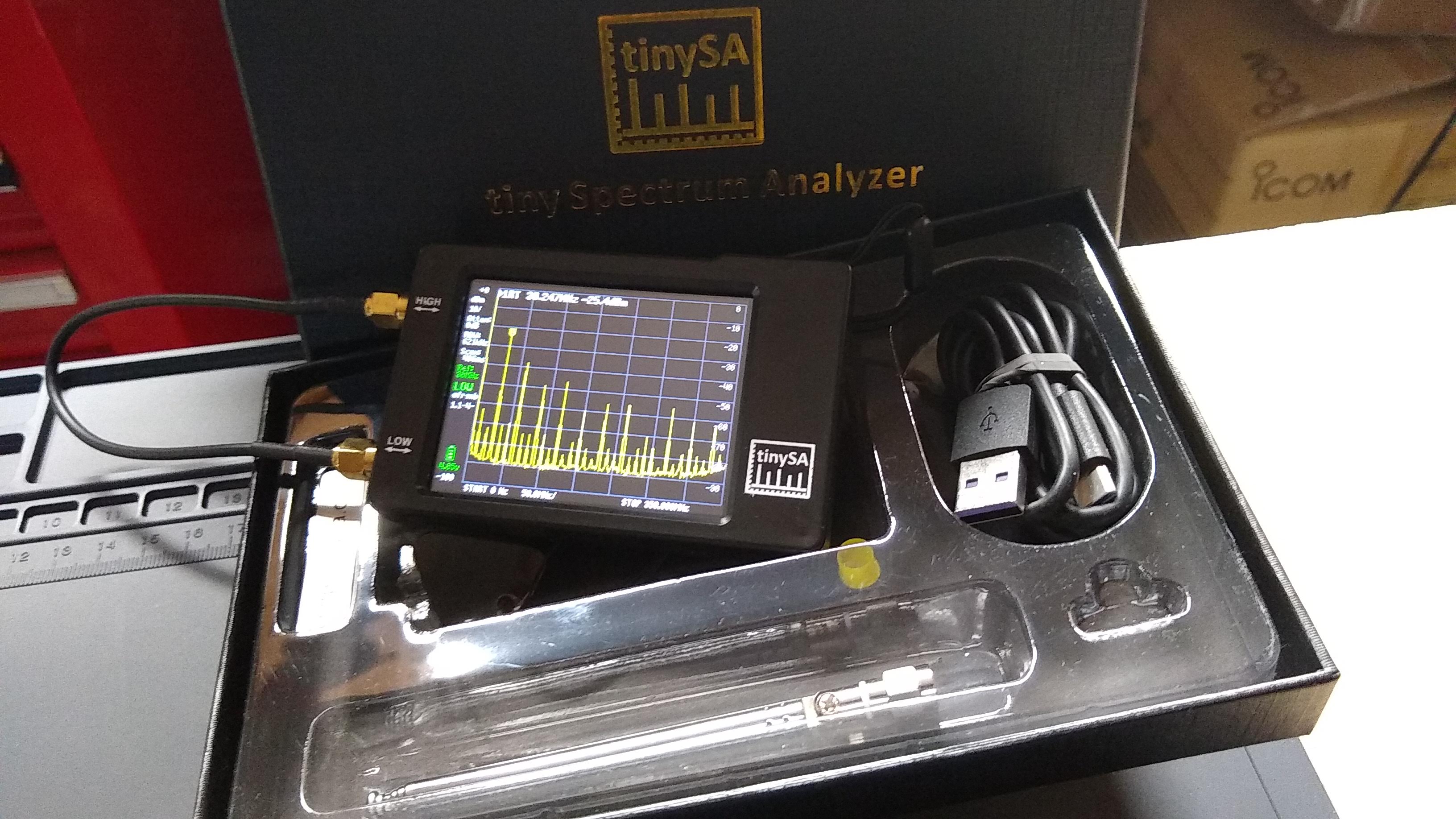
The tinySA arrived in a surprisingly nice “presentation quality” box with a gold-stamped logo on the top. Erik takes pains to note that this is one way to tell you’re getting an original tinySA as opposed to one of the inevitable knock-offs that’ll flood the market soon enough. I’m not sure that alone would keep the pirates at bay, but it’s at least an attempt and it’s a nice touch to boot.
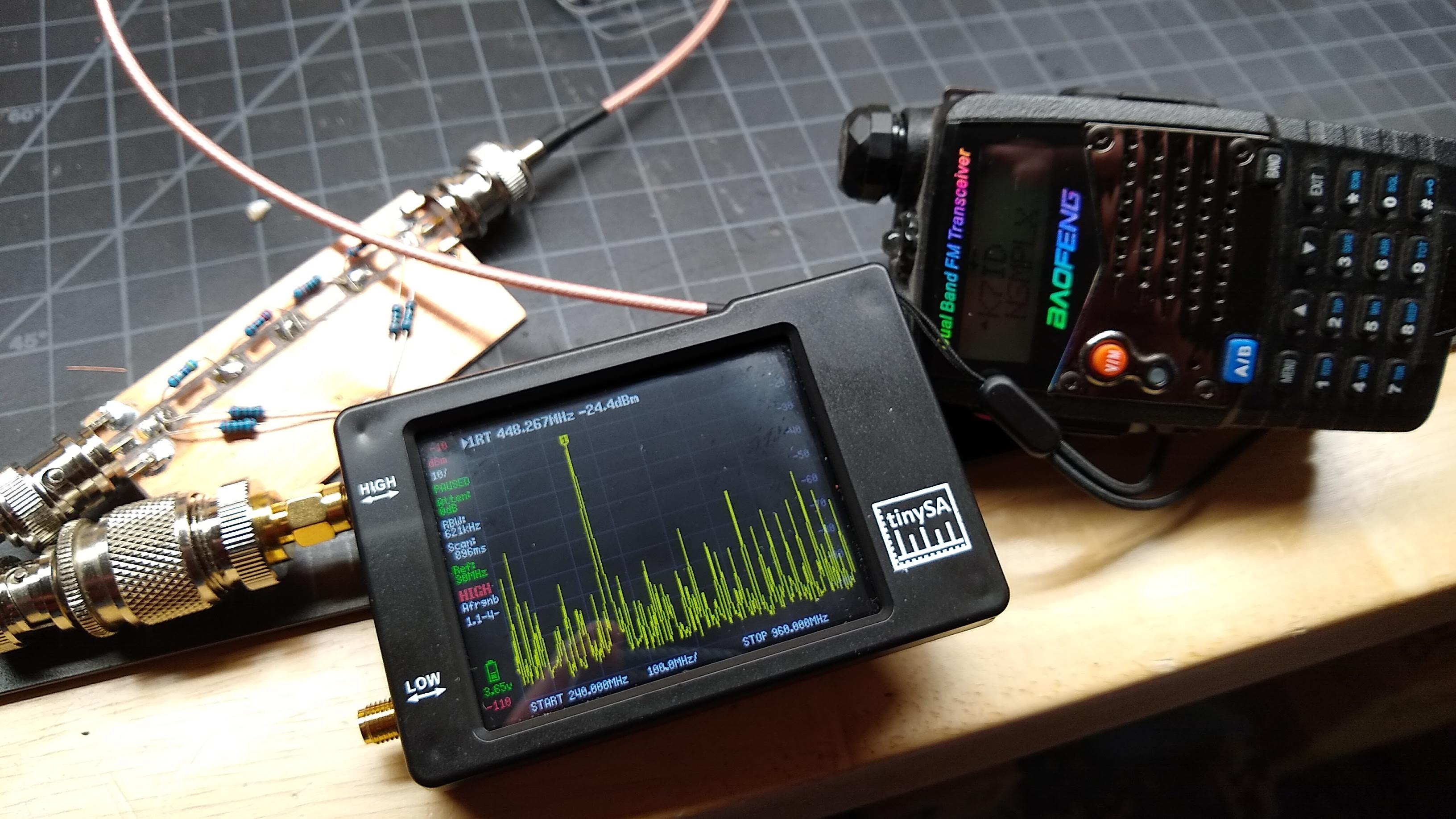
Along with the tinySA, which is about the size of a deck of playing cards, the box contains a pair of SMA jumper cables, a small telescoping whip antenna, a female-to-female SMA adapter, a wrist strap, and a USB-C cable. The case of the tinySA is injection molded ABS, and a nice upgrade in look and feel from the open board design of the NanoVNA. The front of the tinySA has no controls, just the 2.8″ 320×240 resistive touch-screen display. The top has a power switch and a jog control. The left side has two SMA jacks, labeled HIGH and LOW. It’s very lightweight but feels solid in the hand.
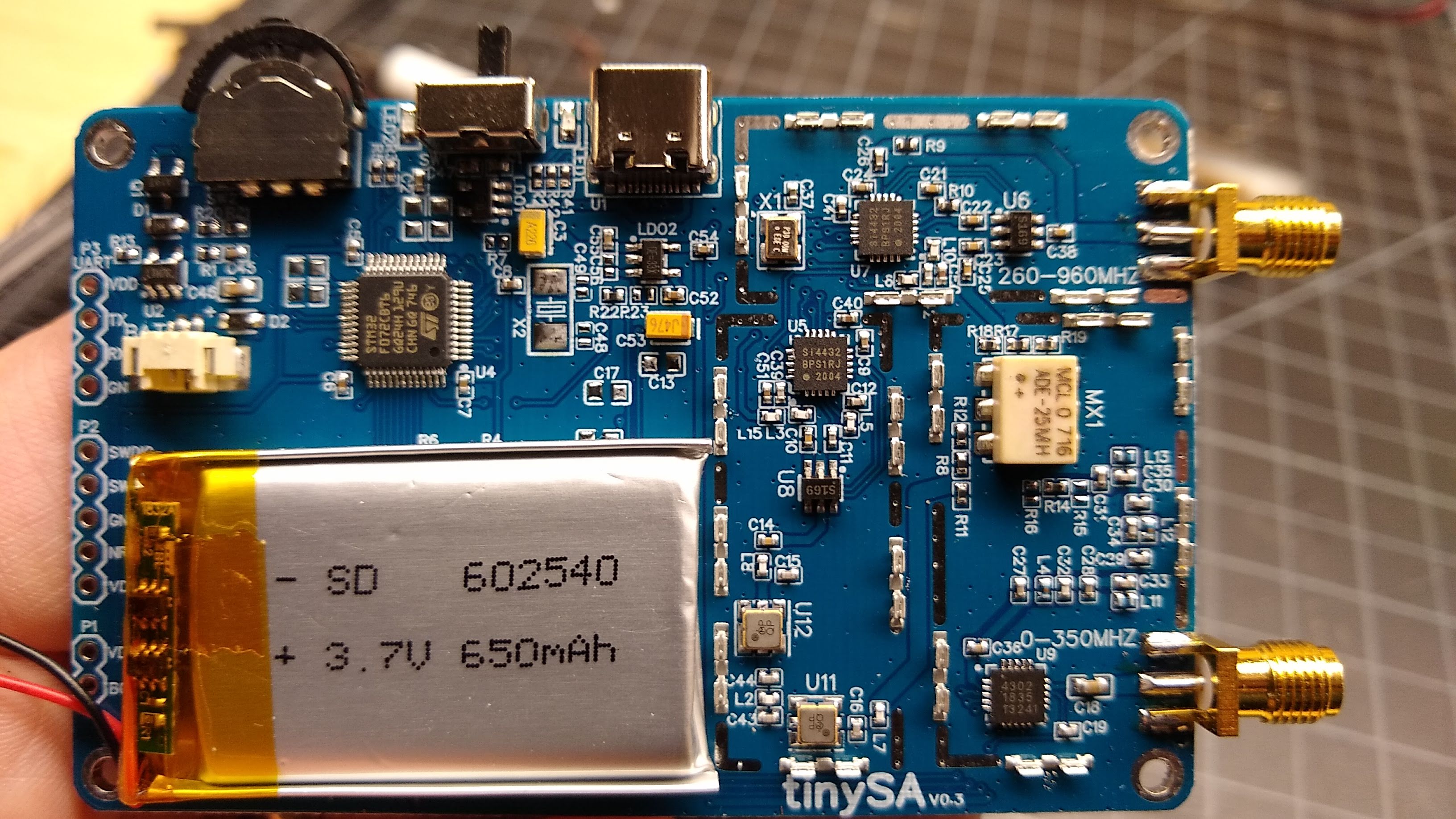
A look inside the tinySA, with the RF shields removed.
Of course the first thing I did was pop the case open and take a look inside. There’s not a lot to see at first — most of the interesting RF stuff is safely tucked under shielding. I figured I’d have to bust out the Hakko to take the tins off, but luckily they’re all spring-clipped to the ground plane, so removing them just took a small screwdriver. Underneath lay the expected RF wizardry, including the expected Silicon Labs chips. I found two Si4432 ISM transceiver chips, presumably one each for the high and low range of the tinySA. There’s also what appears to be a Peregrine Semiconductor PE4302 RF digital attenuator, and a bunch of other goodies. The layout is nice with plenty of via stitching, and the assembly quality is really good.
Satisfied with the insides, I moved on to the “First Steps” as listed in the video below, to get acquainted with the device. Erik has chosen to rely on the tinySA wiki and some how-to videos for most of the documentation, and while that’s understandable it also leaves a few holes that are up to the user to fill in. For those of us who prefer a real manual, Kurt Poulsen, a ham from Denmark, has written up a comprehensive how-to document that might be of help.
Anyone who has used a NanoVNA will feel at home in the tinySA interface. Calibration of the tinySA is done via the built-in signal generator, more on that below. Calibration itself is simple: hook the jumper coax between the two SMA jacks and select LEVEL CAL from the configuration menu. The calibration then proceeds automatically. The same menu offers a self-test function too, which cycles through a series of ten tests that take about 15 seconds to complete.
The Good Stuff
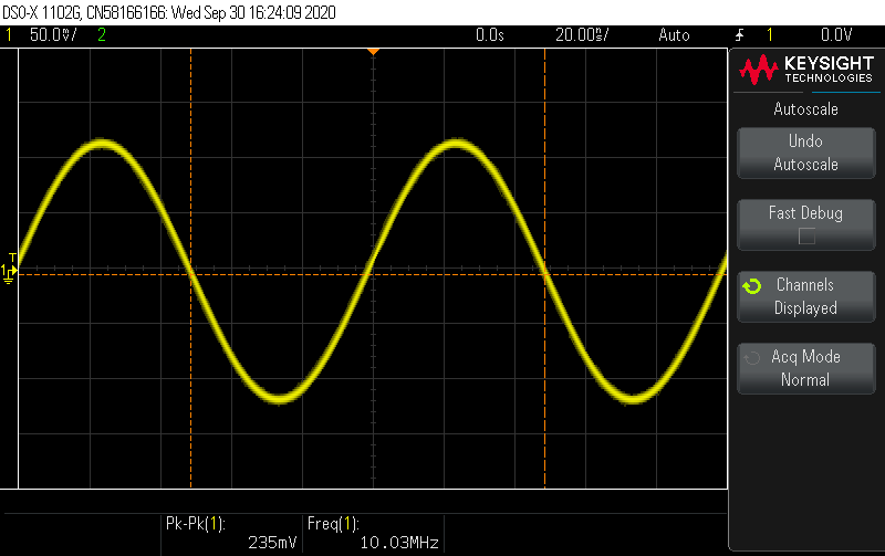
As for its primary purpose, the tinySA performed admirably in my limited tests. I took a look at the spectrum of signals generated by my scope’s built-in waveform generator and everything looked good — a 10-MHz sine wave appears as a single strong fundamental spike and one harmonic about 50 dBm lower. Switching the waveform to a square wave at the same frequency did what I thought it would — a big peak at the fundamental and a bunch of spurs at the odd fundamentals.
Output from the tinySA on my scope – solid, clean 10-MHz sine signal.
With the basics out of the way, I took a look at the tinySA’s built-in signal generator. As mentioned above, the signal generator is used for calibration, but it’s a pretty capable tool all on its own. It’s actually more of a function generator, since it can not only output a nice clean sine wave on the low output between 100 kHz and 350 MHz, but it can also modulate the signal (AM, narrow FM, and wide FM) and do sweeps both across a frequency range and over amplitude. On the high output, the signal generator does a square wave output from 240 MHz to 960 MHz with a configurable, non-sweepable amplitude, narrow FM or wide FM modulation, and a frequency sweep.
I gave the signal generator a go and took a look at its output with my Keysight DSOX1102G. The sine wave generated on the low output looked clean across the specified bandwidth, and the frequency was spot on. I tried playing with the modulation function, and it worked pretty much as I expected. It’ll be nice to have another signal generator around the shop.
My janky test setup: UV-5RA, homebrew 40 dB attenuator, and the tinySA.
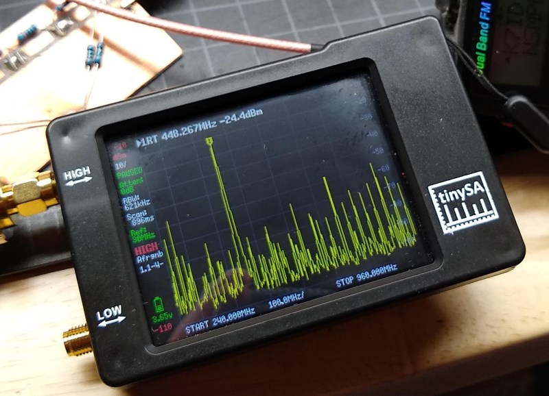
With all the pleasantries dispensed, I turned to the one task pretty much every ham will want to turn a spectrum analyzer on: finding out just how bad the signal from a cheap handy talkie is. I talked about this a bit in one of my $50 Ham articles, and we’ve seen comprehensive analyses of spurious emissions from these radios that are far more in-depth than anything I could come up with using the tinySA. But still, I thought I’d give it a whirl. I grabbed my Baofeng UV-5RA, a homebrew 40 dB attenuator I built a while back, and an unwieldy collection of adapters to connect everything together.
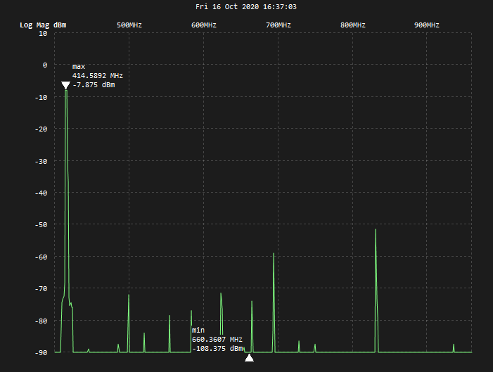
Being under the impression that the spurious emissions on Baofeng tend to be worse on the UHF band, I tried 420 MHz first. The first thing I noticed was that the fundamenal was off a bit from the where it should be. I also noticed a small forest of spurs starting at 500 MHz and extending all the way up past 800 MHz. The strongest spur was about 43 dBm down from the fundamental. The FCC rules on spurious emissions don’t seem to cover this band, but they do say that between 30 and 225 MHz, spurs need to be at least 40 dBm below the fundamental. So within the limits of my test setup, the Baofeng seems to just barely comply.
Spurious emissions from a Baofeng UV-5RA at 420 MHz. The big spur at about 825 MHz is the only one that comes close to exceeding the limits.
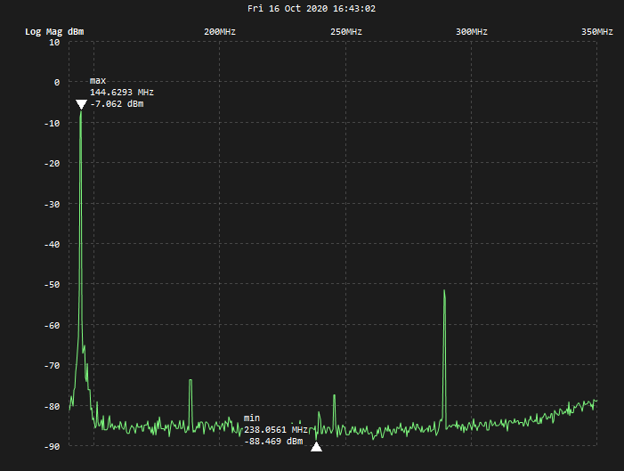
Just for completeness, I repeated the same test on the 2-m band. The signal was much cleaner here, with only a few spurs, the big one being at around 270 MHz. Again, this was about 43 dBm down from the fundamental, meaning it was probably in compliance. Again, this was only a rough test, with a test setup leaving much to be desired. But still, the tinySA is a nice way to take a look at what you’re actually putting out into the ether, and to at least get a rough idea how clean you’re operating.
A much cleaner signal from the same radio on the 2-m band.
The Not-So-Good Stuff
Like the NanoVNA before it, the tinySA has the capability of PC control. The Python program, TinySASaver, is geared mostly toward saving scans from the tinySA, but also provides additional capability, like doing frequency sweeps in segments and exporting data for further analysis. It also implements time-domain reflectometry (TDR) to measure cable lengths and find faults. Sadly, try as I might I was unable to get TinySASaver running on my Ubuntu machine. Erik is pretty clear that the code is still rough, and I’m far from a Python guru so I might be having library problems that would be easy to fix for someone with more experience. Luckily, I was able to scrounge up a decrepit Windows laptop and get a compiled version of another program running, so I didn’t have to resort to cell phone pictures for my screenshots.
I have noticed a couple of other annoying issues. The biggest is that the tinySA appears to crash when you click the screen off of one of the menus. This is annoying, as I often found myself stuck in a menu with no obvious “Back” button, and clicking on the background seemed like an intuitive way to work back to another menu. But this just throws a dump of all the registers up on the screen and locks the thing up. It’s not a huge deal to recover — toggle the power and it’ll boot right back up — but it can be annoying.This bug has been removed recently so this is working as it should by now.
I also found the touchscreen a bit finicky, which was a common complaint with the NanoVNA. The screen is far too small for my meathooks, but without a proper stylus, I resorted to a plastic spudger that worked only most of the time. Of course it was only then that I looked in the box and noticed the wrist strap with the attached guitar pick-like stylus — a thoughtful accessory indeed.
Verdict
I’m not entirely sure what I paid for the tinySA — like I said, I tend to order these things and then just forget about them. But I think it was around $60, and at that price I’d say adding a tinySA to your toolkit is a no-brainer. It’ll never substitute for a larger, full-featured instrument, but if your only need for a spectrum analyzer is to design the occasional filter or check signal quality, the tinySA is a pretty good deal.
Op 15 november 2018 werd vanaf Kennedy Spacecenter de Es’hail 2 gelanceerd richting een geostationaire baan om de aarde en sinds enige tijd is de satelliet te gebruiken door radiozendamateurs.
Met een downlink op 10 GHz en een uplink op 2,4 GHz is de satelliet door amateurs betrekkelijk eenvoudig te gebruiken. Het blijkt dat het ontvangen van de satelliet eenvoudiger is dan gedacht. Thijs, PE1RLN neemt je graag mee in zijn ervaringen bij het ontvangen van de smalband communicatie.
10GHz omzetten
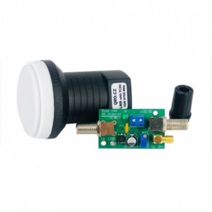
Het ontvangen van een 10 GHz signaal lijkt heel moeilijk maar is met behulp van wat hulpmiddelen erg eenvoudig. Elke satellietschotel heeft een LNB (low noise blockconverter) die het 10GHz signaal van bijvoorbeeld de Astra satelliet omlaag brengt naar circa 900 MHz, een frequentie die al beter te behappen is. Maar voor ons radiozendamateurs geen gangbare frequentie natuurlijk.
De LNB links op de foto kun je vinden bij Passion Radio en deze transformeert het 10 GHz signaal van de Es’hail naar 432 MHz ! Kijk, dan wordt het interessant.
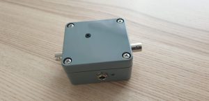
De LNB is voorzien van een 0,5ppm TCXO voor goede stabiliteit en je krijgt er een bias-tee bij om de LNB te voorzien van spanning. Deze werkt namelijk op 12V via de coax. Bij 12V werkt de LNB op vertikale polarisatie, prima voor de smalband transponder. Bij 14-18V werkt hij horizontaal voor de breedband transponder. Voor € 80 heb je ‘m thuisbezorgd binnen een paar dagen.
De IC-9700 transceiver van Icom kan op de antenne-aansluiting ook 12V tijdens RX afgeven, dan heb je de bias-tee niet nodig.
De lokale oscillator in de LNB werkt op 10.057 MHz dus bijvoorbeeld het PSK baken op 10.489,750 MHz ontvang je straks op 432,750 MHz.
Schotel
Schotels zijn voor shoarma én om satellieten te ontvangen. Thijs had nog een 35cm campingschotel liggen en die bleek prima te functioneren voor ontvangst! Dus investeer niet in grote radiotelescopen, 35cm volstaat. Zorg dat je een stevig statief hebt want het uitrichten komt een beetje precies.
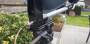
De LNB wordt voorop gemonteerd en wel zodanig dat deze een “skew” heeft van -15,9 graden. Dat betekent dat de LNB gekanteld wordt met de wijzers van de klok mee als je over de LNB heen naar de schotel kijkt. Dat heeft te maken met de kanteling (skew) van de polarisatie van de satelliet zelf. Hoe beter de skew is afgeregeld, hoe sterker het signaal.
Aansluiten
De LNB en de bias-tee zijn voorzien van F-connectoren, zeer gebruikelijk bij satelliet-TV. Thijs heeft achter op de schotel een BNC aansluiting gemaakt en heeft de bias-tee in een kastje ingebouwd met BNC-connectoren. De impedantie klopt niet helemaal en dat levert verlies op maar de LNB geeft zo’n keihard signaal af dat je dat prima kunt permitteren. Op de bias-tee zit zelfs een attenuator die het signaal dempt en die heb je zeker nodig.
De bias-tee komt dus tussen LNB en ontvanger (tenzij je ontvanger al 12V op de coax heeft) en dan stem je af op 432,750 MHz.
Met het stelknopje in de deksel kun je de attenuation instellen. Aangezien de coax kort is en de LNB een hard signaal geeft, kun je deze best zo instellen dat bij een normale RF gain je waterfall weinig ruis laat zien zodat signalen goed zichtbaar zijn. Dit is handig bij het uitrichten.
Uitrichten van de schotel
Stel de schotel bijna vertikaal en richt de arm van de LNB richting het zuiden. Draai vervolgens 26 graden naar het oosten (tegen wijzers van de klok in dus).
Kijk voor de duidelijkheid op www.dishpointer.com voor precieze uitrichting van je schoteltje. Een schotel met elevatie-gradenboog op de achterkant is ook gemakkelijk om de beginpositie te vinden.
Als je de ontvanger aanzet met een waterfall display dan zie je bij een juiste uitrichting allemaal signalen opdoemen rond 432,750 MHz. Je zult merken dat de afstelling van de schotel niet ultra-precies is maar als je de RF gain terugdraait dan kun je aan de hand van de S-meter de maximale uitslag zoeken met de schotel.
Je ziet dat de signalen niet heel ver boven de ruis uit komen maar de S/R ratio is prima. De LNB versterkt ook ruis en alleen een grotere schotel maakt het signaal nog schoner. Maar dat levert geen beter signaal op, dit is namelijk al prima.
Luisteren!
Nu kun je met de ontvanger over de hele band draaien, van 432,500 MHz tot 433,000 MHz. Je hoort onderin CW en in het midden de SSB signalen volgens onderstaand bandplan:
Onderstaand een plot van de dekking van de satelliet:
Most of us perceive time as an arrow, a one-way trip into the future. And while that’s true, nature has a way of interpolating circular patterns onto that linear model — day follows night, the seasons progress through the year, and generations are born, live, and die after creating the next generation to do experience the same cycles in the future.
Our star, too, follows this cyclical model, and goes through observable, periodic changes that are of keen interest to solar scientists. So it was with some fanfare that they recently announced that the sun had transitioned into Solar Cycle 25. But what exactly does that mean? Does the Sun’s changing face make much difference to the average person’s daily life? History shows that it can, so it pays to know what we’re in store for over the next couple of decades. Welcome to your primer on Solar Cycle 25.
It Goes to Eleven
For as long as scientists have had the ability to (safely) observe the Sun, they’ve noticed that our star is not the perfect glowing orb it at first appears to be. Galileo was among the first to observe that the Sun was marked by small dark imperfections. Observers began to keep track of these sunspots, noting not only their variable number but the fact that they migrate across the Sun’s surface with time.
It would take almost two and a half centuries for anyone to notice that the periodic nature of the patterns of sunspots. German scientist Samuel Heinrich Schwabe is credited with the discovery of the solar cycle in 1843 after 17 years of observations of the average number of sunspots. Swiss scientists Rudolf Wolf used the observations of Schwabe and others to backtrack through the data back to 1755. For solar science purposes, this was designated the year that Solar Cycle 1 started.
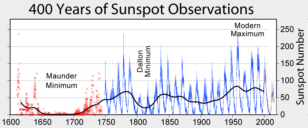
Cycles of sunspots for the last 400 years. The earliest data is estimated from geological and tree-ring records. By Robert A. Rohde, CC BY-SA 3.0
The cycle these pioneering solar scientists had discovered has a remarkably regular eleven-year period. The range of variation is very tight, from the nine-year period of Solar Cycle 2 (1766 to 1775) to almost fourteen years for Solar Cycle 4 (1784 to 1798). Each solar cycle is reckoned from a solar minimum, essentially when the sunspot number reaches its local low. The number of sunspots increases over the first half of the cycle, peaking at the solar maximum point before turning down again to head for the next solar minimum.
The raw number of sunspots is not the only interesting cycle the Sun displays. The distribution of sunspots across the Sun’s surface also changes periodically with the solar cycle. At the beginning of each solar cycle, what few sunspots there are tend to cluster at the Sun’s equator. As the cycle progresses and the Sun becomes more active, the sunspots tend to pop up further away from the equator, generally clustering around the mid-latitudes around 30° north and south. As solar maximum passes, sunspots again migrate back to the equator to start the cycle again.
Flipping Magnetic Poles
The periodic changes in the number and distribution of sunspots may be an interesting observation, but what does it mean here on Earth? To help understand that, it pays to recall that despite their dark appearance, sunspots are only marginally cooler than the surrounding solar material. Sunspots are still extremely energetic areas, and as the number of sunspots increases, the output of the Sun (in terms of luminosity) increases.
Sunspots represent places where concentrated lines of magnetic force emerge from deep within the Sun’s interior. Thus a change in the number and location of sunspots reveals changes in the magnetic field of the Sun. It turns out that what’s behind the solar cycle is these periodic changes in the Sun’s magnetic field. (It’s important to note here that the eleven-year cycle is technically the “sunspot cycle,” and the 22-year pole-flipping cycle is the true “solar cycle,” but it’s common practice to use “Solar Cycle” for both.)
The magnetic poles of the Sun are constantly in motion, with the north and south poles flipping every eleven years. At solar minimum, the magnetic poles are roughly aligned with the Sun’s orbital axis, and magnetic lines of force tend to penetrate the photosphere near the equator. As the poles rotate towards the equator, magnetic activity picks up, magnetic lines of force move to high latitudes, increasing the number of sunspots there. The process continues for the back half of the solar cycle as the poles complete their reversal.
So, as each solar cycle progresses due to the migration of the Sun’s magnetic field, solar output increases. Fractional though these changes are, they have obvious implications for life on Earth. But the increasing brightness of our Sun is far from the only impact felt here. The changing magnetic field of the Sun can also have a huge impact on our planet.
What Happens Next?
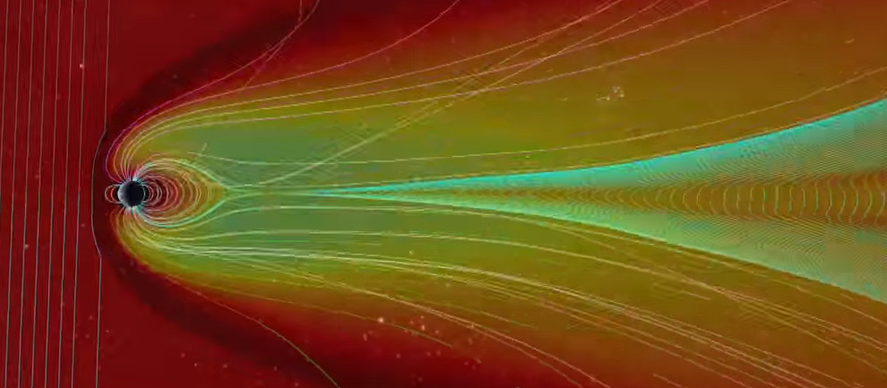
It’s well known that increased sunspots are associated with stronger and more frequent coronal mass ejections, or CMEs. These events, sometimes energetic in the extreme, occur when magnetic domains in the Sun become so twisted and contorted that they erupt outward, picking up gigatons of highly excited plasma from the Sun’s corona. If the CME occurs in just the right spot on the Sun’s surface, the violently ejected tangle of magnetic flux and plasma can strike the Earth, causing anything from an increase in auroral displays to the catastrophic destruction of infrastructure.
While destructive CMEs are more likely to occur during solar maxima — the 1859 Carrington Event occured near the peak of Solar Cycle 10, and the 1989 Hydro-Québec disaster was about seven months before the peak of Solar Cycle 22 — it’s far from a rule that they only occur then. Plenty of damaging or potentially dangerous CMEs have occurred during solar minima. But the number of CMEs goes up dramatically with the sunspot number, so that the Sun launches a few large outbursts each day during a solar maximum. Simply increasing the number of shots increases the chances of a devasting strike.
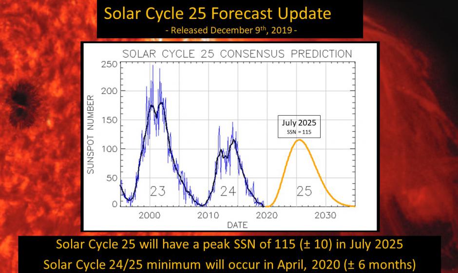
While the increased risk of Earth-striking CMEs during solar maximum is a concern, it’s important to keep in mind a few things. First, solar maximum is still about five years away; NASA says that Solar Cycle 25 officially began in December of 2019, meaning we’re still very much in solar minimum conditions. Second, not all solar cycles are created equal. Layered on top of the eleven-year solar cycle are other periodic cycles that we’re only beginning to understand. One is the Gleissberg Cycle, an 87-ish-year cycle where the solar maxima of the eleven-year cycle tend to increase and decrease. We’re currently in the decreasing phase of the Gleissberg Cycle, meaning that the just-completed Solar Cycle 24 had a much lower solar maximum than the previous cycle. The current prediction is that Solar Cycle 25 will be about the same intensity as the previous cycle at solar maximum, and will reach solar maximum around July of 2025.
The potential for a sleepy sun for the next eleven years is a “good news, bad news” thing. On the plus side, there’s a greatly reduced — but far from zero — risk of experiencing a catastrophic Earth-striking CME. That means less risk to our vulnerable infrastructure, both terrestrial in terms of the millions of miles of power and communications wires we’ve stitched together, and space-based, since satellites can be greatly impacted by space weather. On the other hand, amateur radio operators and others who depend on ionospheric skip for long-range radio communications, like marine operators, airlines, and the military, always get grumpy when the sun is less active, since fewer sunspots mean decreased ionization of Earth’s atmosphere.
In the end, the Sun is going to do what it does, regardless of how it impacts life here on Earth. All we can do is learn everything possible about the star at the center of our solar system, build good models to predict its behavior over time, and build systems that can withstand our star’s mood swings.
While M17 might sound like a new kind of automatic rifle (as actually, it is), we were referring to an open source project to create a ham radio transceiver. Instead of paraphrasing the project’s goals, we’ll simply quote them:
The goal here should be to kick the proprietary protocols off the airwaves, replace DMR, Fusion, D-Star, etc. To do that, it’s not just good enough to be open, it has to be legitimately competitive.
Like some other commercial protocols, M17 uses 4FSK along with error correction. The protocol allows for encryption, streaming, and the encoding of callsigns in messages. There are also provisions for framing IP packets to carry data. The protocol can handle voice and data in a point-to-point or broadcast topology.
On the hardware side, the TR-9 is a UHF handheld that can do FM voice or M17 with up to 3 watts out. The RF portion uses an ADF7021 chip which is specifically made to do 4FSK. There’s also an Arm CPU to handle the digital work.
We were struck by the similarity of the TR-9 to a cell phone since it has an LCD display, an SD card slot, and a 9DOF sensor. Maybe some open hardware cell phones and open hardware ham radios could find common ground.
This is quite ambitious, but generally, small ham rigs are having a resurgence. Having high-quality RF components available as chips makes a lot of difference.
Amateur radio operators and shortwave listeners have a common enemy: QRM, which is ham-speak for radio frequency interference caused by man-made sources. Indiscriminate, often broadband in nature, and annoying as hell, QRM spews forth from all kinds of sources, and can be difficult to locate and fix.
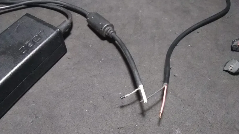
But [Emilio Ruiz], an operator from Mexico, got a little help from Mother Nature recently in his quest to lower his noise floor. Having suffered from a really annoying blast of RFI across wide swaths of the radio spectrum for months, a summer thunderstorm delivered a blessing in disguise: a power outage. Hooking his rig up to a battery — all good operators are ready to switch to battery power at a moment’s notice — he was greeted by blessed relief from all that noise. Whatever had caused the problem was obviously now offline.
Rather than waste the quiet time on searching down the culprit, [Emilio] worked the bands until the power returned, and with it the noise. He killed the main breaker in the house and found that the noise abated, leading him on a search of the premises with a portable shortwave receiver. The culprit? Unsurprisingly, it was a cheap laptop power supply. [Emilio] found that the switch-mode brick was spewing RFI over a 200-meter radius; a dissection revealed that the “ferrite beads” intended to suppress RFI emissions were in fact just molded plastic fakes, and that the cord they supposedly protected was completely unshielded.
We applaud [Emilio]’s sleuthing for the inspiration it gives to hunt down our own noise-floor raising sources. It kind of reminds us of a similar effort by [Josh (KI6NAZ)] a while back.
Sinds kort is in het International Space Station een transponder actief waarmee je in FM flinke afstanden kunt overbruggen. Kijk maar eens op Amsat voor info hieromtrent.
Op maandag 21 september begon er weer een cyclus met zichtbare overkomsten van het ISS en Thijs, PE1RLN besloot om de gok te wagen om na APRS ook een gewoon QSO te voeren. En met succes! Om 22.30 uur kwam het ISS over en al snel was er communicatie te horen. Thijs gaf een CQ en een Duits tegenstation kwam retour en maakte zo het QSO compleet.
Helaas was de verbinding kort en was Thijs verrast door de snelheid dus heeft hij geen callsign genoteerd…
Op 22 september werd het experiment herhaald bij een lage overgang. Door de afstand waren andere stations sterker en was een verbinding niet mogelijk. Maar anderhalf uur later kwam het ISS recht boven Hulsberg en werd er een eerste compleet QSO gemaakt! Luister hier naar het fragment van een nagenoeg kristalheldere verbinding:
 De bias-tee komt dus tussen LNB en ontvanger (tenzij je ontvanger al 12V op de coax heeft) en dan stem je af op 432,750 MHz.
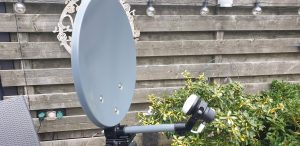 Stel de schotel bijna vertikaal en richt de arm van de LNB richting het zuiden. Draai vervolgens 26 graden naar het oosten (tegen wijzers van de klok in dus).
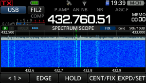 De signalen zijn zeer goed te nemen, alsof het lokale SSB signalen zijn.
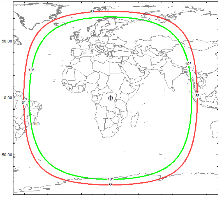

 Sinds kort is in het International Space Station een transponder actief waarmee je in FM flinke afstanden kunt overbruggen. Kijk maar eens op
  Super cool natuurlijk en nu is bij Thijs het hek van de dam…