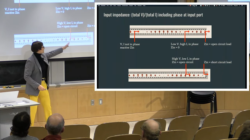
Dealing with an antenna is one of those topics we never feel like we know enough about. MIT had a live stream of [Dr. Kiersten Kerby-Patel] discussing antennas in a talk, sponsored by the ham radio club on campus. You can see the recording below.
The main assertion of the presentation is that everything is a dipole unless it is a loop. Although the professor probably deals with antennas at an extremely high theoretical level, she did a great job of keeping it aimed at ham radio operators.
The talk is about an hour long, so it isn’t optimized for the YouTube generation. There’s some introductory material that looks as though it would have been in one of our old physics classes. However, the talk gets more practical towards the end.
There’s the obligatory mention of Yagis and loops. There’s even a Smith chart. If you don’t know what the Chu limit is, you should definitely be watching this video. The end of the talk covers some very small antennas using active devices or even moving parts.
It may not seem like it, but amateur radio is fighting a two-front war for its continued existence. On the spectrum side, hams face the constant threat that the precious scraps of spectrum that are still allocated to their use will be reclaimed and sold off to the highest bidder as new communication technologies are developed. On the demographic side, amateur radio is aging, with fewer and fewer young people interested in doing the work needed to get licensed, with fewer still having the means to get on the air.
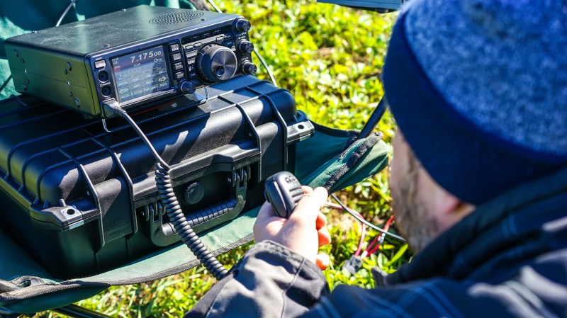
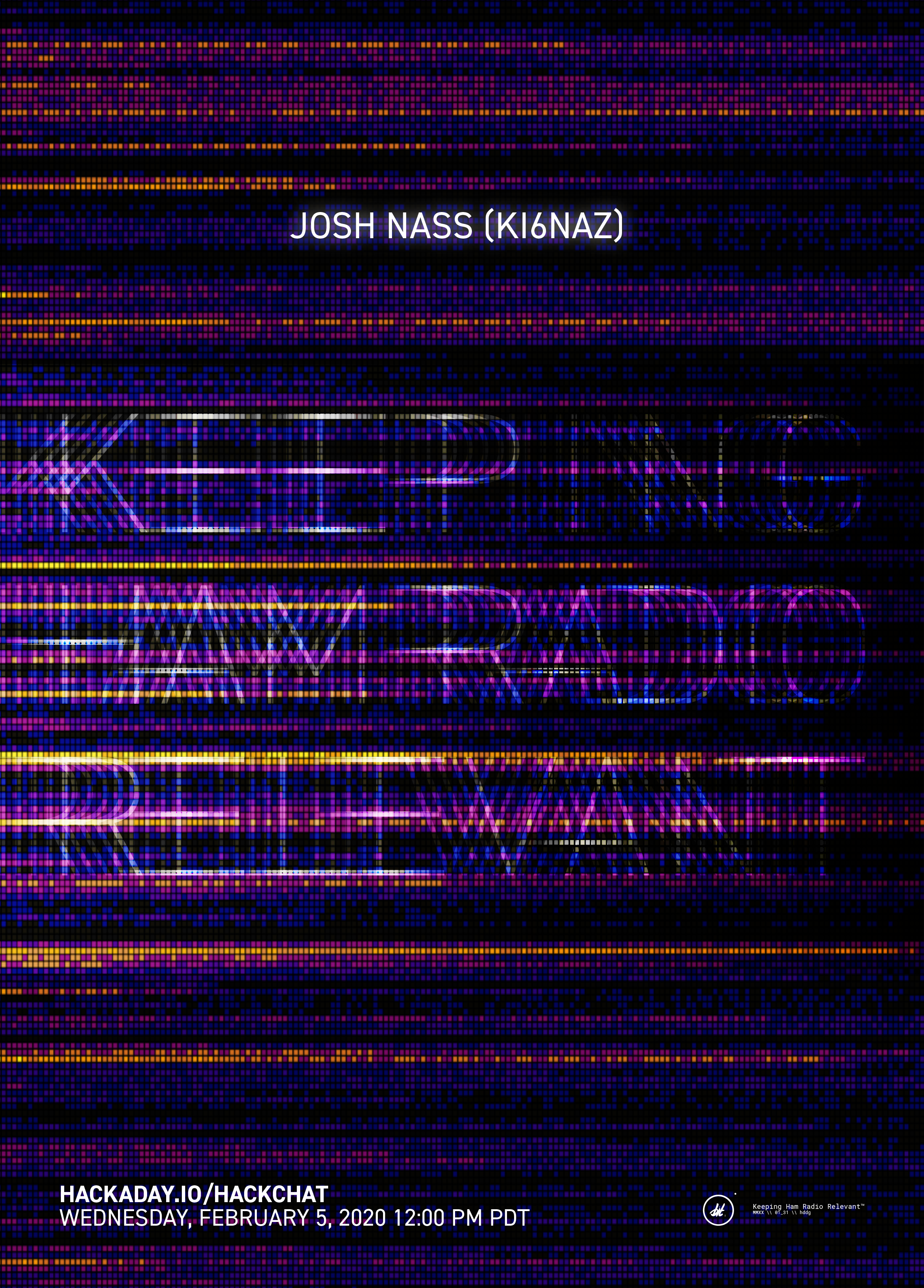
Amateur radio has a long, rich history, but gone are the days when hams can claim their hobby is sacrosanct because it provides communications in an emergency. Resting on that particular laurel will not win the hobby new adherents or help it hold onto its spectrum allocations, so Josh Nass (KI6NAZ) is helping change the conversation. Josh is an engineer and radio amateur from Southern California who runs Ham Radio Crash Course, a YouTube channel dedicated to getting people up to speed on ham radio. Josh’s weekly livestreams and his video reviews of ham radio products and projects show a different side of the World’s Greatest Hobby, one that’s more active (through events like “Summits on the Air”) and focused on digital modes that are perhaps more interesting and accessible to new hams.
Join us on the Hack Chat as we discuss how to make ham radio matter in today’s world of pervasive technology. We’ll talk about the challenges facing amateur radio, the fun that’s still to be had on the air even when the bands are dead like they are now (spoiler alert: they’re not really), and what we can all do to keep ham radio relevant.
Click that speech bubble to the right, and you’ll be taken directly to the Hack Chat group on Hackaday.io. You don’t have to wait until Wednesday; join whenever you want and you can see what the community is talking about.
Conventional wisdom holds that the best way to learn a new language is immersion: just throw someone into a situation where they have no choice, and they’ll learn by context. Militaries use immersion language instruction, as do diplomats and journalists, and apparently computers can now use it to teach themselves Morse code.
The blog entry by the delightfully callsigned [Mauri Niininen (AG1LE)] reads like a scientific paper, with good reason: [Mauri] really seems to know a thing or two about machine learning. His method uses curated training data to build a model, namely Morse snippets and their translations, as is the usual approach with such systems. But things take an unexpected turn right from the start, as [Mauri] uses a Tensorflow handwriting recognition implementation to train his model.
Using a few lines of Python, he converts short, known snippets of Morse to a grayscale image that looks a little like a barcode, with the light areas being the dits and dahs and the dark bars being silence. The first training run only resulted in about 36% accuracy, but a subsequent run with shorter snippets ended up being 99.5% accurate. The model was also able to pull Morse out of a signal with -6 dB signal-to-noise ratio, even though it had been trained with a much cleaner signal.
Other Morse decoders use lookup tables to convert sound to text, but it’s important to note that this one doesn’t. By comparing patterns to labels in the training data, it inferred what the characters mean, and essentially taught itself Morse code in about an hour. We find that fascinating, and wonder what other applications this would be good for.
Het zou zomaar kunnen nu er recent – na een lange periode van afwezigheid – weer zonnevlekken op onze moederster zijn gespot.
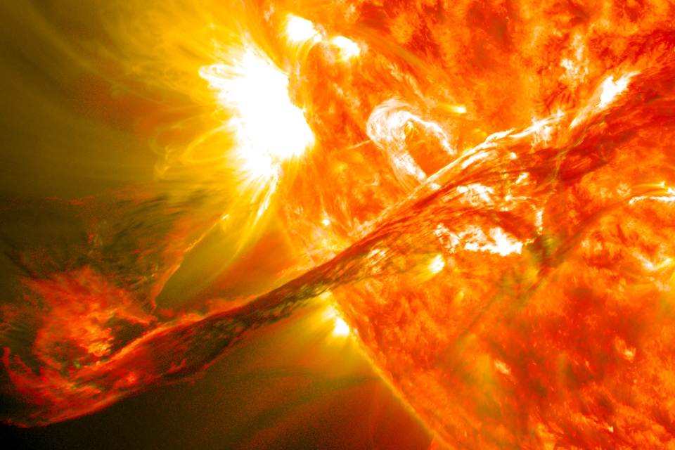
De dag voor kerst zagen astronomen twee groepen zonnevlekken op onze moederster. Nu hoor ik je denken: zo bijzonder is dat toch niet? Nou, de astronomen keken er toch even van op. Want de zon was al sinds 14 november 2019 vrij van zonnevlekken. De laatste keer dat de zon zo’n lange periode zonnevlekvrij was, was in 1996.
Cyclus
Die inactiviteit is te herleiden naar de cyclus van de zon. Onze moederster doorloopt namelijk een grofweg 11 jaar durende cyclus die gekenmerkt wordt door een zonneminimum – een periode waarin de zon heel rustig is en weinig zonnevlekken en zonnevlammen genereert – en een zonnemaximum, waarin de ster juist veel actiever is. Het zonnemaximum vond in 2014 plaats. Sindsdien neemt de activiteit op de zon af en is het wachten op het zonneminimum dat tevens het einde van deze zonnecyclus en het begin van een nieuwe markeert. Onderzoekers voorspelden eerder dat het zonneminimum zich rond april 2020 aan zou dienen. Maar dat kon ook zes maanden later of zes maanden eerder worden; de ervaring leert dat de zon het niet zo nauw neemt met de tijd.
Nu er na een lange periode van rust weer zonnevlekken op de zon opduiken, is de grote vraag of dit dan het zonneminimum was en daarmee dus een nieuwe zonnecyclus is aangebroken. Wetenschappers hebben meer data nodig om met zekerheid te kunnen zeggen dat deze zonnevlekken daadwerkelijk een nieuwe zonnecyclus inluiden, maar dat een nieuwe cyclus aanstaande is, staat vast en wordt door de komst van de zonnevlekken duidelijk onderschreven.
Wat brengt het ons?
Wat die nieuwe zonnecyclus ons brengt, is altijd enigszins koffiedik kijken. De ene cyclus is namelijk de andere niet. Soms verloopt zo’n cyclus – zoals het exemplaar waar we nu nog net (of net niet meer) inzitten – vrij gemoedelijk en is de zon zelfs tijdens het zonnemaximum nog relatief rustig. Maar er zijn ook cycli geweest waarin het zonnemaximum gekenmerkt werd door een hoop onrust op de zon. Die onrust komt tot uiting in veel zonnevlekken, zonnevlammen, en meerdere zogenoemde coronale massa-ejecties per dag. Met name die coronale massa-ejecties kunnen nog weleens venijnig zijn; tijdens deze uitbarstingen op de zon worden energierijke deeltjes en magnetische velden de ruimte ingeslingerd. Deze kunnen behalve een fraai poollicht genereren, ook schade aanrichten aan satellieten in een baan rond de aarde en – in uitzonderlijke gevallen – zelfs voor problemen zorgen op aarde (zie kader).
Onze aarde wordt omringd door een magnetisch veld dat ons onder meer beschermt tegen de grillen van de zon. Maar heel soms schiet dat aardmagnetisch veld tekort. Dat kan gebeuren als er sprake is van een samenloop van omstandigheden die leidt tot een extreme, op de aarde gerichte, uitbarsting op de zon. Dat gebeurde bijvoorbeeld in 1859. Een coronale massa-ejectie raakte toen de aardse magnetosfeer – de invloedssfeer van het magnetisch veld dat de aarde zelf genereert – waardoor deze verstoord raakte. Het leidde tot het uitvallen van de telegraafverbinding tussen Europa en Amerika. En in 1989 zorgde de zon er zo voor dat een elektriciteitsnetwerk in Canada werd uitgeschakeld en zo’n zes miljoen mensen meer dan negen uur zonder stroom zaten.
Gezien de impact die een actieve zon op de aarde en omgeving kan hebben, is er onderzoekers veel aan gelegen om te kunnen voorspellen wat een zonnecyclus gaat brengen. Maar dat is zo gemakkelijk nog niet. Want nog steeds weten we niet precies hoe onze ster met name diep van binnen werkt. Toch wagen sommige onderzoekers zich wel aan een voorspelling. En die is enigszins geruststellend. Naar verwachting wordt de volgende zonnecyclus net als de cyclus waar we nu in zitten (of net uit zijn gerold) vrij rustig. Sterker nog: NASA voorspelde vorig jaar dat het wel eens de zwakste zonnecyclus in 200 jaar tijd zou kunnen worden, waarbij de intensiteit van het zonnemaximum – gemeten in het aantal zonnevlekken – 30 tot 50% lager ligt dan in de meest recente zonnecyclus. Het zou goed nieuws zijn voor de plannen van NASA, die in 2024 – dus rondom het zonnemaximum – mensen naar de maan wil sturen en daar geen gevaarlijk ruimteweer bij kan gebruiken.
Next time you get a new device and excitedly unwrap its little poly-wrapped power supply, remember this: for every switch-mode power supply you plug in, an amateur radio operator sheds a tear. A noisy, broadband, harmonic-laden tear.
The degree to which this fact disturbs you very much depends upon which side of the mic you’re on, but radio-frequency interference, or RFI, is something we should all at least be aware of. [Josh (KI6NAZ)] is keenly aware of RFI in his ham shack, but rather than curse the ever-rising noise floor he’s come up with some helpful tips for hunting down and eliminating it – or at least reducing its impact.
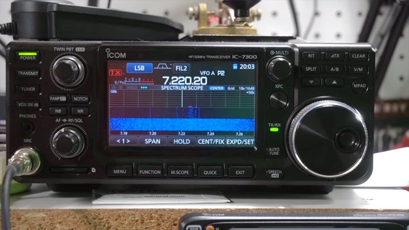
Attacking the problem begins with locating the sources of RFI, for which [Josh] used the classic “one-circuit-at-a-time” approach – kill every breaker in the panel and monitor the noise floor while flipping each breaker back on. This should at least give you a rough idea of where the offending devices are in your house. From there, [Josh] used a small shortwave receiver to locate problem areas, like the refrigerator, the clothes dryer, and his shack PC. The family flat-screen TV proved to be quite noisy too. Remediation techniques include wrapping every power cord and cable around toroids or clamping ferrite cores around them, both on the offending devices and in the shack. He even went so far as to add a line filter to the dryer to clamp down on its unwanted interference.
Judging by his waterfall displays, [Josh]’s efforts paid off, bringing his noise floor down from S5 to S1 or so. It’s too bad he had to take matters into his own hands – it’s not like the FCC and other spectrum watchdogs don’t know there’s a problem, after all.
The radio spectrum is carefully regulated and divided up by Governments worldwide. Some of it is shared across jurisdictions under the terms of international treaties, while other allocations exist only in individual countries. Often these can contain some surprising oddities, and one of these is our subject today. Did you know that the UK’s first legal CB radio channels included a set in the UHF range, at 934 MHz? Don’t worry, neither did most Brits. Behind it lies a tale of bureaucracy, and of a bungled attempt to create an industry around a barely usable product.
Hey, 2019, Got Your Ears On?
Did this car make you want a CB radio? Stuurm [CC BY-SA 3.0]
Mention CB radio in 2019 it’s likely that the image conjured in the mind of the listener will be one from a previous decade. Burt Reynolds and Jerry Reed in Smokey and the Bandit perhaps, or C. W. McCall’s Convoy. It may not be very cool in the age of WhatsApp, but in the 1970s a CB rig was the last word in fashionable auto accessories and a serious object of desire into which otherwise sane adults yearned to speak the slang of the long-haul trucker.If you weren’t American though, CB could be a risky business. Much of the rest of the world didn’t have a legal CB allocation, and correspondingly didn’t have access to legal CB rigs. The bombardment of CB references in exported American culture created a huge demand for CB though, and for British would-be CBers that was satisfied by illegally imported American equipment. A vibrant community erupted around UK illegal 27 MHz AM CB in the late 1970s, and Government anger was met with campaigning for a legal allocation. Brits eventually got a legal 27 MHz allocation in November 1981, but the years leading up to that produced a few surprises.
Governments tend to be their happiest when in the driver’s seat, and thus they were reluctant to simply licence the same CB allocation as the American one. During the protracted period of campaigning by CBers over the end of the decade it became obvious that there was a very significant demand for an allocation but they could not be seen to let the illegal CBers win. Their first tactic was to propose a 928 MHz UHF allocation with a 500mW power limit which was rejected by the CB lobbyists, so the final allocation became a 27 MHz one with a 4W limit on an odd set of frequencies incompatible with the American ones, and using FM rather than the American AM. Alongside this they clung to a UHF allocation, which was finally given at 934 MHz.
The result was that Brits had two CB allocations, one of which on 27 MHz that worked even if it wasn’t as good as the American sets, and one on 934 MHz that didn’t work very well at all and had eye wateringly expensive equipment. All the wannabe Rubber Ducks gravitated towards 27 MHz, but 934 MHz became an exclusive pursuit for enthusiasts; essentially another amateur band in which propagation and DX chasers plied their craft.
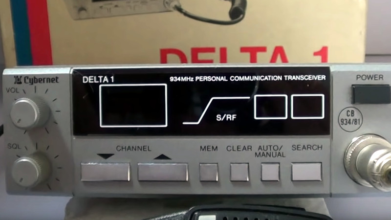
The Government hoped that having two CB allocations unique to the UK would create a home-grown industry supplying British-made CB rigs, a seductive idea for politicians with little knowledge of how the electronic hardware industry works. For example, the same idea has been touted in recent years as a reason behind drone licencing laws. But in reality, the market was soon flooded with UK-spec 27 MHz radios from Far Eastern manufacturers. By contrast 934 MHz rigs were rare, with only one or two models being brought to market. The object of desire was the Cybernet Delta One, a video review of which we’ve placed at the bottom of the page.
Christmas 1981, The Day The Dream Ended
If you were an AM CBer who bought a legal UK 27 MHz FM rig in November 1981, then life continued as usual as the community moved to the new band. They had a triumphant couple of months as victors savouring their spoils, but then Christmas came around, and everyone who’d sat in the cinema watching Convoy and fantasised about CB lingo got a rig of their own. Overnight the dream was shattered, followed swiftly by the UK CB bubble bursting as the novelty wore off. 27 MHz CB continues in the UK with a set of European channels now added to the UK ones, but never again will it be anything approaching cool.
Meanwhile the 934 MHz channels continued to provide an experimentation ground for enthusiasts, and every month in Practical Wireless there was a column devoted to its propagation. In 1988 as the mobile phone industry began to expand, there was a demand for UHF frequencies, and the Government stopped the sale of new 934 MHz equipment. A decade later the allocation was officially removed, and those 934 MHz rigs are now illegal to use, though they do still appear in radio rallies from time to time.
The UK CB boom had a surprising effect, in that it brought a whole new audience into radio as a hobby and caused a corresponding boom throughout the 1980s as many of those people went on to obtain their amateur licences. If you meet someone with a G1 callsign there’s a good chance that’s the generation they came from, so ask them if they had a 934 MHz radio. Even if they didn’t, they’ll probably be able to tell you more about this interesting side chapter in radio history.
Now, sit back and enjoy M0OGY’s review of a 934 MHz radio.
We’ve frequently talked about amateur radio on these pages, both in terms of the breadth of the hobby and the surprisingly low barrier to entry. It’s certainly the case that amateur radio does not have to mean endlessly calling CQ on SSB with an eye-wateringly expensive rig, and [Bill Meara N2CQR] is on hand with a description of a transceiver that’s so simple it only uses one transistor.
It’s a 40 meter (7 MHz) QRP or low power transceiver in which the transmitter is a simple crystal oscillator and the receiver is an equally simple regenerative design. What makes it so simple is the addition of a three-way switch to transfer the single transistor — a J310 FET — between the two halves of the circuit. It’s no slouch as QRP radios go, having clocked up real-world contacts.
This circuit shows us how a little can go a long way in the world of amateur radio, and we can’t help liking it for that. It’s worth saying though that it’s not without flaws, as a key click filter and another transistor would make for a much higher quality transmitted signal. But then it would no longer be a single-transistor rig, and thus would miss the point, wouldn’t it.
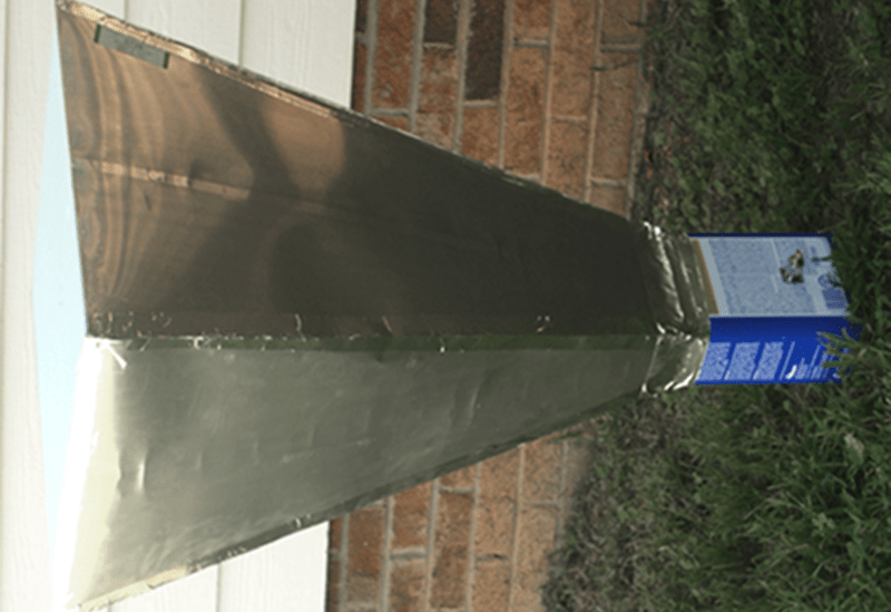
[David Schneider] asked himself, “How big a radio antenna would you need to observe anything interesting?” The answer turns out to be a $150 build of a half meter antenna. He uses it to detect the motions of the spiral arms of the Milky Way. The first attempt was a satellite TV dish and a cantenna feed, which didn’t work as the can wasn’t big enough to pick up signals at the 21cm wavelength of hydrogen emissions. Interstellar gas clouds are known to emit radio energy at this frequency.
Looking online, [David] tried aluminized foam board insulation, but was worried that the material didn’t seem to actually be conductive. A quick thrown-together Faraday cage with a cell phone didn’t seem to block any calls. Abandoning that approach, he settled on aluminum flashing used for roofing.
The roll of flashing was ten feet long and 20 inches wide, so that limited the antenna’s design. Still, an online calculator showed a theoretical gain of 17dB. A can still shows up in the final build — a paint thinner can.
There was a time when picking a receiver for a project such as this would be a challenge. Nowadays you can just pick up an RTL-SDR and you are good to go. The setup is sensitive enough to pick up the frequency of gas clouds and detect the Doppler shift between the arms heading towards us and those traveling away from us.
Depending on your goals, you can use a TV dish for radio astronomy work. Probably none of these will pick up what the Chinese can hear with their new 500 meter installation.
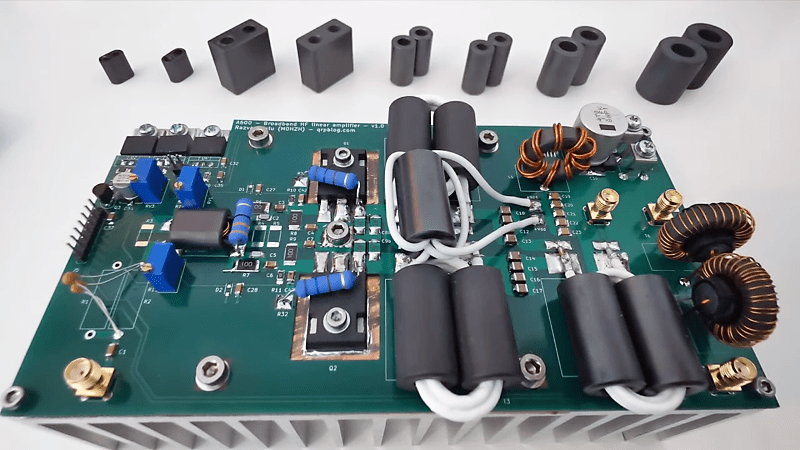
Typically, amateur radio operators use the minimum power needed to accomplish a contact. That’s just part of being a good spectrum citizen, and well-earned bragging rights go to those who make transcontinental contacts on the power coming from a coin cell. But sometimes quantity has a quality all its own, and getting more power into the ether is what the contact requires. That’s where builds such as this well-engineered 600W broadband RF amplifier come into play.
We’re really impressed with the work that [Razvan] put into this power amp. One of the great joys of being a ham is being able to build your own gear, and to incorporate the latest technology long before the Big Three manufacturers start using it. While LDMOS transistors aren’t exactly new – laterally-diffused MOSFETs have been appearing in RF power applications for decades – the particular parts used for the amp, NXP’s MRF300 power transistors, are pretty new to the market. A pair of the LDMOS devices form the heart of the push-pull amp, as do an array of custom-wound toroids and transformers including a transmission line transformer wound with 17-ohm coax cable. [Razvan] paid a lot of attention to thermal engineering, too, with the LDMOS transistors living in cutouts in the custom PCB so they can mate with a hefty heatsink. Even the heatsink compound is special; rather than the typical silicone grease, he chose a liquid metal alloy called Gallinstan. The video below gives a tour of the amp and shows some tests with impressive results.
All of us have experience in trying to explain to a confused store assistant exactly what type of kitchen implement you’re looking for, and why it is a perfectly suitable part for your autonomous flying lawn mower. Or in the case of [MM0OPX] trying to find fly fishing reels that are suitable for his Adjustiwave multi-band VHF-HF ham radio antenna.
HF radios allow intercontinental communication but require very large antennas which can be tricky to tune properly, and this antenna helps ease both these problems. The basic configuration is quarter wave, linear loaded (folded), vertical antenna. A quarter wave length radiator wire runs up a fibreglass pole, folds over the top, and comes back down, to form a shorter, more practical antenna while remaining the required length. Ground plane radial wires are usually added to improve performance by helping to reflect signals into antenna.
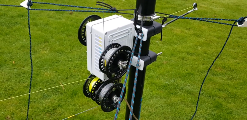
[MM0OPX] expanded this concept by using two pairs of fly fishing reels to quickly adjust the length of the radiators and radials. One reel holds the actual antenna wire while the second holds fishing braid, which is tied to the end of the wire to provided tension. The radials wire is exactly the same, it just runs across the ground.
The four reels are mounted to a plastic junction box, which houses the feed line connector and matching transformer, which is attached to the base of a fibreglass pole with hydraulic pipe clamps. Each wire is marked with heat shrink at defined points to allow quick tuning for the different frequencies. [MM0OPX] tried a couple of wire types and found that 1 mm stainless steel cable worked best.
This being Hackaday, we are big fans of repurposing things, especially when the end product is greater than the sum of its parts, as is the case here. Check out the walk around and build discussion videos after the break.
If you’re keen to get your ham radio license and try your hand at HF, it’s possible to get a fully featured µBITX transceiver kit to build your own, as well as an antenna analyser, all thanks to [Ashhar Farhan]’s RF hacking skills.


![Did this car make you want a CB radio? Stuurm [CC BY-SA 3.0]](https://hackaday.com/wp-content/uploads/2019/10/1978_Trans-Am_bandit.jpg)