While M17 might sound like a new kind of automatic rifle (as actually, it is), we were referring to an open source project to create a ham radio transceiver. Instead of paraphrasing the project’s goals, we’ll simply quote them:
The goal here should be to kick the proprietary protocols off the airwaves, replace DMR, Fusion, D-Star, etc. To do that, it’s not just good enough to be open, it has to be legitimately competitive.
Like some other commercial protocols, M17 uses 4FSK along with error correction. The protocol allows for encryption, streaming, and the encoding of callsigns in messages. There are also provisions for framing IP packets to carry data. The protocol can handle voice and data in a point-to-point or broadcast topology.
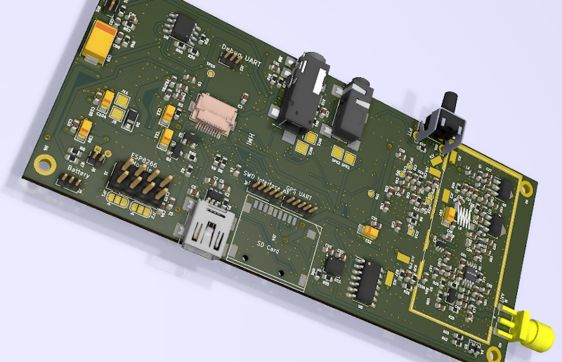
On the hardware side, the TR-9 is a UHF handheld that can do FM voice or M17 with up to 3 watts out. The RF portion uses an ADF7021 chip which is specifically made to do 4FSK. There’s also an Arm CPU to handle the digital work.
We were struck by the similarity of the TR-9 to a cell phone since it has an LCD display, an SD card slot, and a 9DOF sensor. Maybe some open hardware cell phones and open hardware ham radios could find common ground.
This is quite ambitious, but generally, small ham rigs are having a resurgence. Having high-quality RF components available as chips makes a lot of difference.
Amateur radio operators and shortwave listeners have a common enemy: QRM, which is ham-speak for radio frequency interference caused by man-made sources. Indiscriminate, often broadband in nature, and annoying as hell, QRM spews forth from all kinds of sources, and can be difficult to locate and fix.
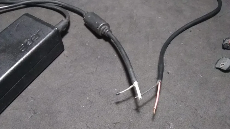
But [Emilio Ruiz], an operator from Mexico, got a little help from Mother Nature recently in his quest to lower his noise floor. Having suffered from a really annoying blast of RFI across wide swaths of the radio spectrum for months, a summer thunderstorm delivered a blessing in disguise: a power outage. Hooking his rig up to a battery — all good operators are ready to switch to battery power at a moment’s notice — he was greeted by blessed relief from all that noise. Whatever had caused the problem was obviously now offline.
Rather than waste the quiet time on searching down the culprit, [Emilio] worked the bands until the power returned, and with it the noise. He killed the main breaker in the house and found that the noise abated, leading him on a search of the premises with a portable shortwave receiver. The culprit? Unsurprisingly, it was a cheap laptop power supply. [Emilio] found that the switch-mode brick was spewing RFI over a 200-meter radius; a dissection revealed that the “ferrite beads” intended to suppress RFI emissions were in fact just molded plastic fakes, and that the cord they supposedly protected was completely unshielded.
We applaud [Emilio]’s sleuthing for the inspiration it gives to hunt down our own noise-floor raising sources. It kind of reminds us of a similar effort by [Josh (KI6NAZ)] a while back.
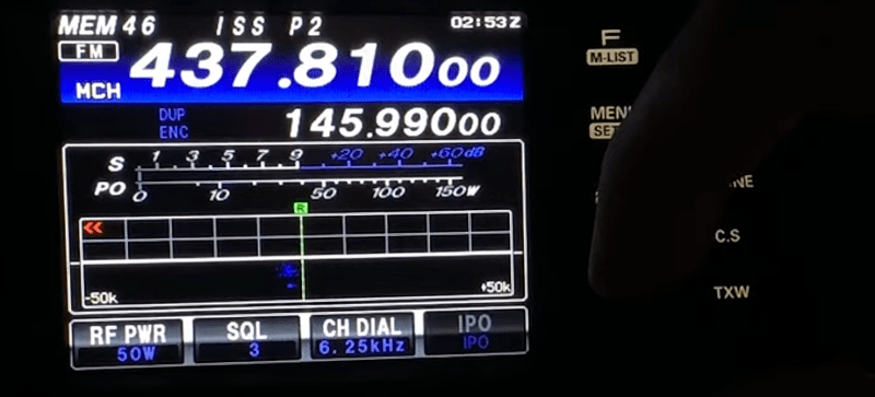
There is a long history of spacecraft carrying ham radio gear, as the Space Shuttle, Mir, and the ISS have all had hams aboard with gear capable of talking to the Earth. However, this month, the ISS started operating an FM repeater that isn’t too dissimilar from a terrestrial repeater. You can see [TechMinds] video on the repeater, below.
The repeater has a 2 meter uplink and a 70 centimeter downlink. While you can use a garden variety dual-band ham transceiver to use the repeater, you’ll probably need a special antenna along with special operating techniques.
One of the problems you’ll find is that ISS moves fast enough that you will observe doppler shift in the frequencies. The video reproduces a table of frequencies you may have to move through to receive the shifting signal.
You can probably hear the ISS with a good pass with no special equipment, but [TechMinds] wasn’t able to close an actual contact in the video. But [K0LWC] got really close using a pretty standard radio setup, as you can see in the second video.
The ISS has been on the air with digital repeaters and conventional FM radio for some time. The antenna you need doesn’t have to be a huge disk. We’ve seen it done with a handheld beam antenna and a handheld radio.
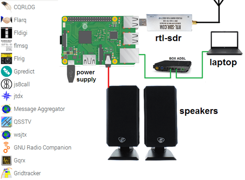
There was a time when a ham radio set up sported many dials and switches and probably quite a few boxes as well. Computers have changed all that. Some transceivers now have just a few buttons or are even totally computer-controlled. Where a ham, at one time, might have a TeleType machine, a slow-scan TV monitor, and a fax printer for receiving satellite images, now that can all be on a single computer which can even be a Raspberry Pi. [F4GOH] has a post that takes you from the fundamentals to installing everything from an SDR to many common ham programs for digital modes, APRS, SSTV, and more. You can download the seven-part tutorial as separate PDF files, too.
Even if you aren’t a ham, you might find some of the software interesting. OpenWebRX lets you listen to your software defined radio on the road. You can use other software to pick up weather satellite data.
If you are a seasoned Linux user, you won’t need some of the early material. But you will find some good notes on how to use the ham-specific software and get a good overview of what is possible.
Ham radio has changed a great deal. If you think of it as people with noisy large radios, you might be surprised. The hobby is big enough that you’ll find everything from people talking on tiny radios around the world using a hybrid of radio and Internet connectivity, to people bouncing signals off the moon or using ham radio satellites.
[Dan Maloney] has talked about how to get started in ham radio for under $50. Then again, you might need another $50 for the Raspberry Pi. Of course, there are plenty of opportunities to hack the gear.
For most of us, electronic technology comes in the form of solid state devices. Transistors, integrated circuits, microcontrollers. But for the first sixty years or so of the field existing, these devices either hadn’t been invented yet or were at too early a stage in their development to be either cost-effective, or of much use. Instead a very different type of electronic component ruled the roost, the vaccum tube.
A set of electrodes in an evacuated glass envelope whose electrical properties depended on the modulation of the flow of electrons through them, these were ubiquitous in consumer electronics up until the 1960s, and clung on in a few mass-market applications even as far as the mid 1970s. As cheaper and more versatile semiconductors superseded them they faded from electronic parts catalogues, and the industry that had once produced them in such numbers disappeared in favour of plants producing the new devices. Consumer products no longer contained them, and entire generations of engineers grew up never having worked with them at all. If you were building a tube amplifier in the early 1990s, you were a significant outlier.
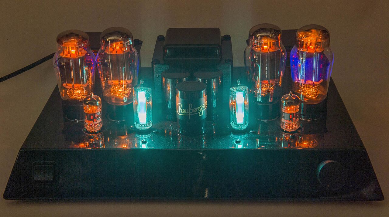
Alive And Kicking In The 21st Century
The warm glow of a tube amplifier lends credibility to an audiophile set-up. Hannes Grobe / CC BY-SA 4.0.
As our consumer electronics have become ever more digital in their make-up, interest has blossomed in analogue devices, or at least devices with a visibly analogue component. In particular the world of audio has begun to chase the elusive “tube sound”, whether it be in the context of intentionally overdriven amplifiers for the guitarist, or closer to perfect ones for the audiophile.
High-end hi-fi shops are full of tube-based devices, and a plethora of tube amplifier kits are available for the electronics enthusiast. Tubes can be bought under a bewildering array of brands often at eye-watering prices, something of a surprise for a technology which might be presumed to have disappeared over four decades ago. This does raise an interesting question though, with such a large number of tube brands on the market, where are they all made, and how have their manufacturers survived for so long? The answer is relatively straightforward, yet in other aspects a story of labyrinthine complexity.
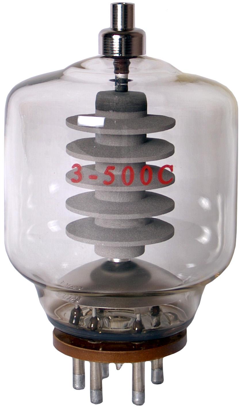
High-power transmitting tubes never went away. Angeloleithold (CC BY-SA 3.0)
While consumer vacuum tubes might have disappeared from mundane electronics decades ago, it’s first worth pointing out that many of the old names in the vacuum tube business didn’t stop manufacturing vacuum tubes, they simply stopped making the tubes you might be familiar with. There are industrial applications in which vacuum devices are very much still with us , even though in many cases they have semiconductors snapping at their heels.
High power RF amplifiers for UHF and higher frequencies for example still use vacuum tubes, be they specialised planar tubes or slightly more exotic fare such as klystrons. Similarly there are specialised RF applications that still use travelling wave tubes, and very high power industrial equipment that uses vacuum and gas-filled tubes for control or rectification.
But who is making the “normal” tubes — the smaller glass-envelope tubes, small triodes and pentodes such as you’d find in that guitar amplifier? We recognize some names from times past such as Telefunken or Mullard, others are modern brands such as JJ or Fender’s Groove Tubes brand, and others are clearly Russian or Chinese names such as Svetlana, SovTek, “Winged C“, or Shuguang. Clearly there are not as many tube factories left in the world as there are logos stamped on the glass of imported tubes, so what on earth is going on?
A Technology For The Few, Not The Many Any More
The answer is that the consumer tube business in 2020 is no longer a commodity component market producing the lifeblood of a million televisions and radios, instead it’s a boutique operation serving a niche market. Looking at the tubes available, it’s clear that if you are searching for an obscure 1050s small-signal RF tube you’ll be out of luck; these are mostly audio amplifier parts, double triodes, output pentodes, even the occasional power rectifier, and at costs that would raise an eyebrow or two for buyers of their originals.
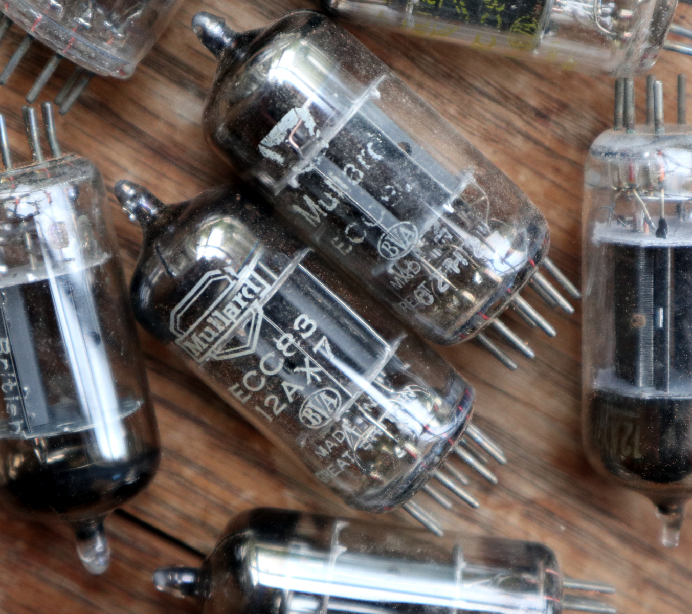
A current-manufacture Mullard-branded ECC83 (12AX7) general purpose small signal double triode for example costs $43.20 (£35.09) in 2020, while browsing a 1957 copy of Wireless World we find the same part number advertised for 8 shillings and thruppence, which is £0.41 ($0.51) in post-decimalisation British money. Using the Bank of England’s inflation calculator that comes out at about £9.96 ($12.27) today, so the modern re-issue is more than three times as expensive as was the genuine article in its heyday. This is evidently a business with a significant mark-up, and the world’s remaining tube factories are cashing in.
A selection of Mullard ECC83s from back in the day.
Investigating further, we find that tube manufacture of this type appears to be entirely absent from the Americas and Western Europe. It survived the decline of the 1970s in Russia, China, and the formerly Communist states of eastern Europe, and as Soviet communism fell and the Chinese economy grew in the 1990s it emerged from the shadows to supply the audio market. These count among them factories that have been in the tube business for a very long time indeed, and their products have many proven decades of reliable service.
So if you buy a tube with a Western sounding brand name today it will have been made in the same Eastern factories as those with an obviously Communist heritage, and thus given that the same part numbers are available from the same sources under those cheaper brands it’s difficult not to wonder whether or not they are in fact exactly the same tubes but with an inflated price.
In the Slovak Republic are JJ, a very long-established tube manufacturer who were previously the consumer end of the Tesla vacuum device range. They don’t admit to branding their tubes for anyone else on their website, but they are reputed to be the source of those Telefunken-branded parts. Moving eastwards to Russia we then find SED-SPb in St. Petersburg, for whom consumer tubes are listed on the website as a small part of their range alongside industrial and high-power RF vacuum devices. They were previously the producers of the Svetlana range of tubes through the Soviet era, and though they no longer have that brand name they retain the winged C logo from that era. It’s unclear whether they are still involved in the production of branded tubes as their website is not very informative, but the “Winged C” tubes manufactured by them are still on sale.
Further across Russia in the southern Russian city of Saratov is the Expo-PUL factory, and here is where the story becomes interesting. It’s owned by the American Electro-Harmonix company, who in turn hold the rights for a host of older brands including Svetlana, Sovtec, Mullard, and Tung-Sol. It’s here that reissued Mullard ECC83 is made, and it has made the news in the past as Russian mobsters reportedly tried to seize it.
PSVane are definitely marketing their tubes such as this 300B as desirable high-end products.
Into China, and the situation becomes rather opaque. China has a selection of larger manufacturers who produce tubes to a very high quality for the high-end export trade, but there are also inexpensive tubes on the market with scant manufacturer logos and little else in the way of traceability. If you pay $20 for an AliExpress tube headphone amplifier kit then it’s likely you’ll receive one of this latter variety, but its origins will be unclear.
The largest Chinese manufacturer is ShuGuang, based in Changsha, in Hunan province. They manufacture a large range as well as producing components for other brands. Their upstart competitor PSVane is also based in Changsha, and concentrates specifically on the high-end audio market. It’s unlikely for example that a 45 cent 6j1 small-signal pentode will have come from either of these two manufacturers or their smaller high-end competitors though, so it’s clear that there are more Chinese tube manufacturers at all levels of the market than can easily be found from the other side of the world.
Is It Really Worth It Though?
As someone who has been a vacuum technology enthusiast for four decades now it makes me happy to find that tubes are still in production and their industry appears healthy for now. But my tour through the world of 21st century tube manufacture leaves me slightly disappointed that so much of their marketing is still clouded by mythology.
As someone who was building tube amplifiers with Yugoslavian TV tubes back when it was extremely unfashionable, I understand the allure of that elusive “tube sound”, but experience has taught me that it’s not as great a thing as its proponents would have you believe. Even the distortion characteristics sought by musicians can more easily be created through DSP in 2020, so I can’t help the feeling that people are being led astray as I see essentially the same tube being sold at a range of different prices based solely on its brand. Enjoy working with tubes, and enjoy listening to a tube amplifier. But don’t make the mistake of falling into the trap of falling for the hype, and never lose sight of the engineering.
Modern radio receivers have a distinct advantage over the common early designs which I covered in my previous article. Most of the receivers you will have worked with over the past couple decades are designs by Edwin Armstrong; regenerative, superregenerative, or most commonly superheterodyne. These are distinguished by a few fascinating key traits that bring both benefits and drawbacks.
Today let’s dive into Mr. Armstrong’s receivers. I’ll also talk about DC receivers which, despite the name, are not made to listen to batteries. These are receivers you are much more likely to encounter in modern equipment.
Regenerative and Superregenerative
The regenerative receiver is all about doing more with less. You still see some of these in simple applications like RF remote controls. The idea derives from how an oscillator works. In a simple way of thinking, an oscillator is an amplifier with enough positive feedback that any tiny signal at the right frequency will amplify and then, through feedback, continue to output over and over. If everything were perfect, then, an oscillator would have infinite gain at a given frequency.
Of course, things aren’t perfect, but they are close enough. You have to set the feedback network up just right to get the frequency you want. Also, things in nature tend to be linear, so it isn’t like the amplifier has no gain at the given frequency and then suddenly has infinite gain. The gain increases until it meets the Barkhausen criteria and achieves stable oscillation.
In fact, sometimes we want to build an amplifier and find that it oscillates for some reason. Maybe that’s what made Edwin Armstrong think about the regenerative receiver. In it, an amplifier is pushed almost to the point of oscillation at the frequency of interest. This can result in a huge gain for a single tube or transistor. This was especially important when using low-quality active devices. For example, a tube capable of a gain of 10 without regeneration might amplify between 5,000 and 10,000 times when it was right on the edge of oscillation.
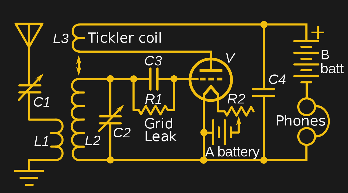
That’s a big improvement and meant that a very simple device could pick up very distant radio signals. There are many ways you could arrange positive feedback. However, the most common way (as in the accompanying schematic) was to have a pickup coil called a tickler around the primary tuned circuit coil. If that coil was out of phase, you’d get negative feedback, so common advice on this kind of radio was that if it didn’t work after you built it, try reversing the leads of the tickler.
The superregenerative was another design by Armstrong. It is essentially the same circuit, but after a certain frequency higher than the bandwidth of interest, the design stops the oscillation action allowing it to build again. Armstrong called this quenching. This could improve gains into the neighborhood of a million times. Armstrong’s original demonstration of the concept showed a three-tube receiver that was as sensitive as a nine-tube conventional design.
There are some downsides to both of these designs, though. You usually have to adjust the regeneration and the circuit can easily go into oscillation, producing a squeal. It also radiates signal back out the antenna, so it is a sort of transmitter. This is bad for interference or — for military applications — where you wish not to be found. If you want to build your own, we’ve had some advice for you in the past, including someon a breadboard. If you prefer, you can just simulate one that [Qrp Gaijin] demonstrates in the video below.
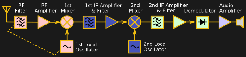
Superheterodyne
Armstrong was also behind the most successful architecture of all, the superheterodyne. If you have a non-software defined radio, it probably uses this technique. The idea is simple and has to do with selectivity. Consider the TRF radio. You can get better performance by putting more stages ahead of the detector. But each stage has to cover the entire range of the radio and requires tuning when you change frequency.
Armstrong’s idea was to limit that. You may or may not have one relatively broad filter in front of a mixer that adds (and subtracts) two RF signals. Then a local oscillator provides another signal to the mixer. Suppose you want to receive a signal at 1 MHz and you set the local oscillator to 9 MHz. You’ll get a signal at 10 MHz (and 8 MHz). You can now filter that 10 Mhz signal and amplify it using filters and amplifiers that you don’t have to tune (at least, not more than once). This makes their design simple and is also less hassle for the operator.
Now, if you want to receive a signal at 1.1 MHz, you change the local oscillator to 8.9 MHz. You still get a 10 MHz signal. If there is a station at 1.2 MHz, you’ll also get a signal at 10.1 MHz, but since you have the 10 MHz filters and amplifiers, you can get rid of that easily. That 10 MHz, in this example, is the IF or intermediate frequency.
This is a great way to build a radio. You can pile on gain and selectivity by adding more IF stages. The only real downside, as I mentioned in the last article is the possibility of images. Because the mixer both adds and subtracts, you can hear a station at the wrong frequency. Consider our 1 MHz signal with a local oscillator frequency of 9 MHz. A 19 MHz signal at the antenna will also show up at the 10 MHz output of the mixer since 19-9=10, just like 1+9=10.
There are several ways to get over that. First, you can filter before the mixer. That’s why a lot of radios have a band switch — well, it is at least one of the reasons. You select a filter that roughly cuts out the interference from images. High-quality receivers will use dual conversion where one mixer produces one IF signal that is later mixed again to form a second one. Some will even use more conversions to optimize filtering.
There are several ways this can help. Image frequencies are always at twice the local oscillator frequency. Going back to the 1 MHz signal example, the image is at 2×9+1=19 MHz. So the higher the IF, the easier it is to filter off images. As a silly example consider if the 1 MHz receiver used an IF of 61 MHz. Now the local oscillator will run at 60 MHz and the image frequency will be at 121 MHz. It is trivial to filter 1 MHz from 121 MHz.
The problem is that using a higher IF makes it more difficult to reject stations adjacent in frequency. In our extreme example, filters to select between 61 MHz and 61.02 MHz are going to be more complex and costly than ones that select between 10 MHz and 10.02 MHz. Granted, there are surface acoustic wave filters and other devices that can do the job, but typically the best performance for a given cost is going to go to the lower frequency filters and amplifiers.
If you want a nice overview of the superheterodyne that isn’t too technical, check out the video below.
Direct Conversion
The direct conversion (DC) receiver has seen a resurgence in use since many software defined radios use this as a front end before digitizing the signal. You can think of a DC receiver as superheterodyne where the local oscillator doesn’t produce an IF, but instead is set to the frequency you want to receive. That means the output is the detected radio signal.
Using our 1 MHz example, to tune it in, you set the local oscillator to 1 MHz. The output is what you’d normally process with an audio amplifier (in the case of AM radio). The design has several practical problems. If the local oscillator isn’t locked to the transmitting station, the output will be incorrect. With SDR, that’s not a problem because the SDR software can track any shifts, but if you don’t have a computer handling things, it requires a lot of components to stay on frequency (essentially, a phase locked loop).
On the other hand, images are all at low frequencies and easily rejected. A lot of simple ham radio receivers use this technique because you don’t need a lot of frequency-specific amplifiers and filters that require tuning.
Getting Started Receiving
If you want to start designing receivers, the best bet is to build some and see how they work. It is hard to beat the simplicity and performance of a regenerative receiver. Sure, a crystal set is easier, but it won’t pick up like a regen. Using the NE602 or NE612 mixer is a handy way to make a direct conversion receiver with only a little more work. You can use that same mixer in a superhet design, but it is definitely more work.
Even if you are using SDR, you usually need some kind of front end. There are a few more exotic designs we didn’t talk about. If you want to read about Hartley, Barber Weaver, and other interesting topics, A Texas A&M presentation on the topic will fill you in.
Of course, the best way to learn is to go build something! There’s no shortage of design ideas for every kind of radio we’ve discussed. Once you start tweaking on real hardware, you’ll quickly find out what works and what doesn’t.
Acknowledgment: Most of the pretty pictures of block diagrams and schematics were adapted from public domain sources on Wikipedia, particularly from [Chetvorno]. What a great resource.
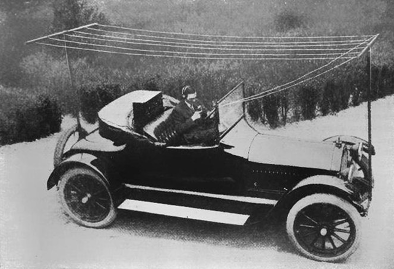
You used to be able to tell a die-hard ham radio operator on the road by the number and length of antennas protruding porcupine-like from their vehicle. There are still some mobile high frequency operators that have respectable car-mounted antenna farms, but they have nothing on Alfred H. Grebe. In 1919, he fitted a medium wave transmitter in his car that operated around 2 MHz. Since it needed a very large antenna, Grebe rigged a wire antenna that looked like a clothesline between the two bumpers. Obviously, you had to stop, set up your antenna, and then operate — you couldn’t talk and drive. But this may have been the world’s first automotive radio setup for voice communication.
The car had a separate battery for the radio and a dynamotor to generate high voltage for the tubes. Although many radio enthusiasts found ways to add receivers to their cars in the 1920s, it would be 1930 before Motorola made radios especially for cars in production quantities.
That wasn’t what Grebe was most famous for, though. He worked as a ship’s operator After making a few receivers for friends, he decided to open up a business. Grebe radio, though, is hardly a household name today. But he was best known for setting up radio stations, including founding the station that would eventually become WCBS, often called the father of news radio.
A dipole antenna is easy, right? Two wires, each a quarter wavelength long, emanate from a coax or other feedline. Unless it is an off-center dipole. The length is still the same, but you move the feed point to a different part. [KB9VBR] explains how this changes the antenna’s impedance from the nominal 70 ohms of a standard dipole.
Why would you want to do that? The trick is to find a feed point that has acceptable impedance on multiple ham radio bands. Most automatic tuners can handle a certain range of mismatch so using an antenna like this with a tuner can allow one antenna to serve multiple bands with no traps or switches.
[KB9VBR] uses a 4:1 balun to convert the relatively high impedance to something close enough for a tuner to work with. A cordless soldering iron comes in handy for antenna work and in the video you can see a gas-powered iron making short work of the connections to the 14 gauge wire.
The impedance also depends on height and he suggests 30 feet, at least. Does it work? If you watch the end of the video, it apparently does. If you are in the mood for technical talk about ham antennas, you could do worse than watch this MIT video. If you want a novel take on why antennas work, you might want to read about the kink.
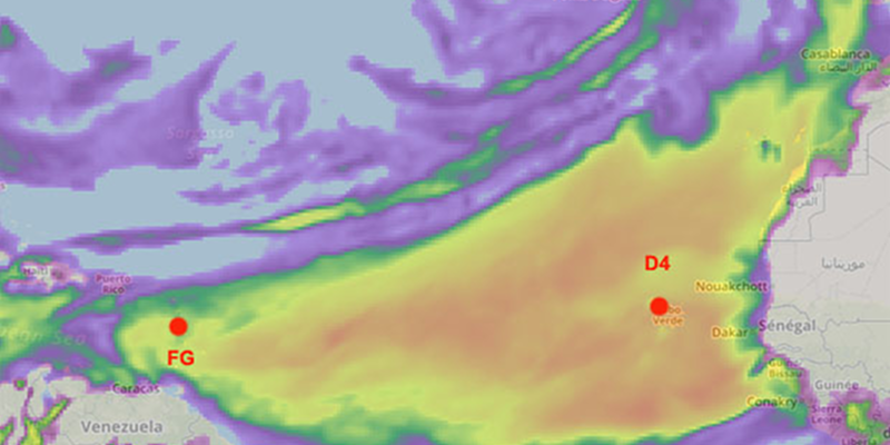
We often think of ham radio operators talking to exotic faraway lands, and that’s true for hams using the HF bands (below 30 MHz), especially if they have nice antennas. Modern living has made it much harder to have those big antenna farms, and today’s ham is more likely talking on VHF or UHF frequencies with very limited range under normal circumstances. Sure, you can use a repeater or bounce your signal from a satellite or the moon, but normal direct communication is normally going to be less than a typical commercial FM radio station. But on April 7th, two hams communicated across the Atlantic on 432 MHz — a UHF frequency. The distance was almost 4,000 km.
Notice we didn’t say they talked, but they communicated. The contact was via a somewhat controversial mode called FT8 which uses weak signal techniques to allow two computers to send limited amounts of information to each other. However, on April 10, the two stations reported a single sideband voice contact after they noticed the band conditions improving on the FT8 signal.
The two stations had good equipment, but nothing out of the ordinary. FG8OJ in Guadeloupe used a 100W transmitter and an 18 element yagi which is not terribly large at that frequency. D4VHF was on the Cape Verde Islands at the time of the contact. FG4ST also made a connection with D4VHF using only a vertical antenna.
Propagation was, obviously, very good to allow this to happen (the image above is from F5LEN’s prediction for that day). The theory is that the signals rode close to the ocean waves in a mode known as ducting. There were other reception reports, so the incident wasn’t isolated.
Normally this kind of thing requires active or passive bouncing of a signal. Repeaters have a limited range. The moon and satellites can take you further but require some work. Hams have even used reflections from airplanes as an in-between solution.
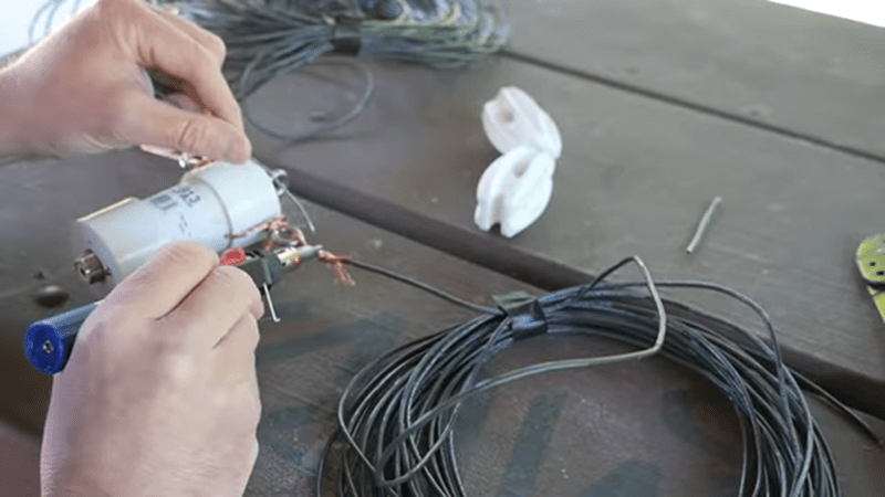
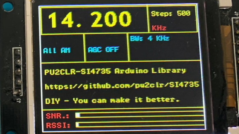
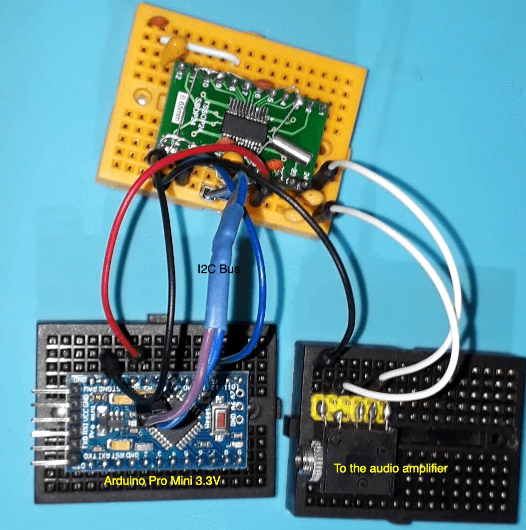
The Silicon Labs Si4735 is a single-chip solution for receiving AM, FM, and shortwave radio. With a bit of hacking, it even supports single sideband (SSB). All you’ve got to do is provide it with a suitable control interface, which [Ricardo Lima Caratti] has done with his recent project.
Using an Arduino Pro Mini, a handful of buttons, and a standard TFT display, [Ricardo] has put together a serviceable little receiver with a fairly impressive user interface. We especially like the horizontal bars indicating the signal to noise ratio and received signal strength. The next evolution would be to put this whole rig into some kind of enclosure, but for now he seems content to control the action with a handful of unlabeled buttons on a piece of perfboard.
Of course, the presentation of this receiver isn’t really the point; it’s more of a proof of concept. You see, [Ricardo] is the person who’s actually developed the library that allows you to control the Si4735 from your microcontroller of choice over I2C. He’s currently tested it with several members of the official (and not so official) Arduino family, as well as the ESP32.
The documentation [Ricardo] has put together for his MIT licensed Arduino Si4735 library is nothing short of phenomenal. Seriously, if all open source projects were documented even half as well as this one is, we’d all be a few notches closer to world peace. Even if you aren’t terribly interested in adding shortwave radio reception to your next project, you’ve got to browse his documentation just to see where the high water mark is.